PiXtend V2 -L- Hardware Manual
6.6. Special Inputs and Outputs
Some inputs and outputs of PiXtend V2 -L- have special functions.
The functions and the associated possibilities are described in detail in the following. See
the PiXtend V2 -L- software manual for software configuration and usage information.
6.6.1.PWM / servo-outputs
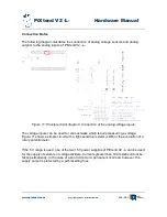
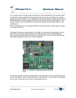
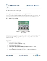
The six PWM outputs are located on the 6-pin connector between the digital outputs and
the PiXtend power supply. On these special outputs either pulse-width-modulated (PWM)
signals with adjustable frequency and duty cycle can be output or RC servos can be
connected directly.
Applications
–
Position of up to six RC servos
–
Speed control of fans and other DC motors
–
Clock for stepping motor driver
–
Dimming of DC lamps and light-emitting diodes (also high-power LEDs)
–
Controlling the temperature of heating elements
–
Precisely adjustable clock source for a variety of electronics applications
www.pixtend.com
Copyright by Qube Solutions GmbH
125 / 146
Figure 78: Terminal bock - PWM/RC
servo outputs

