PiXtend V2 -L- Hardware Manual
Connection Notes
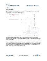
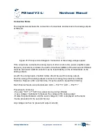
The diagram below shows the connection of consumers and devices to the analog outputs
of PiXtend.
If the outputs are connected to analog inputs of other control units, power amplifiers (also
frequency converters) or similar, the earth connections (GNDs) of the devices and PiXtend
must be connected. A GND connector can be found directly on the terminal block of the
analog outputs.
As with the analog inputs, shielded cables should be used for analog outputs.
The fine-tuning of the analog outputs is carried out during the production of Qube
Solutions. However, after a certain time, it may be useful to repeat this trimming:
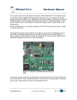
Each channel has its own potentiometer: AO0 → Poti “T0”, AO1 → Poti “T1”
Procedure for trimming:
- the value "10 V" or "1023" (raw value) can be set by software
- Use a voltage / multimeter to measure the voltage at the analog output
- Rotate the potentiometer until the exact voltage of 10.0V is displayed on the meter
- Same procedure for the second channel
Any voltage can then be preset and output correctly.
www.pixtend.com
Copyright by Qube Solutions GmbH
123 / 146
Figure 76: Principle circuit diagram: Connection of the analog voltage outputs


