


PiXtend V2 -L- Hardware Manual
–
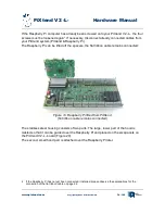
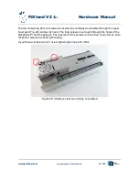
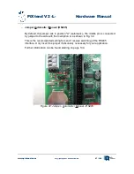
Jumper for RS485- & CAN bus termination
In addition to the connection blocks for RS485 & CAN, there is another three-pin
connection strip each - Fig. 33. No jumper is plugged in as factory default - the
termination with 120 Ω terminating resistor is not active.
By inserting the jumper between the middle pin and the pin with the label ON, the
termination is activated. Whenever PiXtend represents the first or last node of a
bus, it is recommended to activate the termination.
Further information can be found starting on page 134 (RS485) & 138 (CAN).
www.pixtend.com
Copyright by Qube Solutions GmbH
48 / 146
Figure 33: Jumper - RS485 termination
Figure 34: Jumper - CAN termination


