PiXtend V2 -L- Hardware Manual
6.4. Digital inputs and outputs
PiXtend V2 -L- has a wide range of digital inputs and outputs. This chapter contains all
relevant technical data as well as connection and safety instructions. Always read the
relevant sections before you begin wiring and working on inputs or outputs.
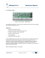
6.4.1.Digital inputs
The 16 digital inputs (DI0 - DI15) are implemented in 1-wire connection technology and
have a reference to the general ground (GND).
Applications
–
Switches, buttons, limit switches
–
Sensors with switching output (proximity switches, light barriers)
–
Outputs of other control units
–
Outputs of integrated circuits (TTL level, CMOS level)
Two different voltage ranges can be set (one jumper per input). In the 24 V range, the
inputs correspond to the specifications of the PLC standard IEC 61131-2. Signals with a 12
V level (for example, in the car / automotive applications) are reliably detected, over-
voltages and polarity reversals up to +/- 30 V can not affect the inputs.
The 5V range is designed for 5V TTL and 3.3V CMOS levels.
Analog filter stages increase the immunity to interference and ensure the reliable signal
processing by the PiXtend microcontroller. LEDs indicate the state of the inputs.
www.pixtend.com
Copyright by Qube Solutions GmbH
88 / 146
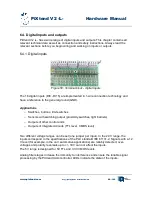
Figure 58: Terminal block - digital inputs


