PiXtend V2 -L- Hardware Manual
Connection notes
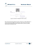
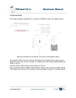
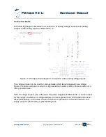
The following diagram illustrates the connection of signal generators to the PiXtend GPIOs
during operation as inputs.
For the supply of sensors, switches and other signal transmitters, one of the +5V supply
connections can be used, which are located on the terminals of the analog inputs and
outputs. Care must be taken to ensure that a maximum of 100 mA current can be taken
from the supply connection. In case of doubt, a self-resetting fuse (polyfuse) protects the
supply connection from overload and short-circuit.
If a temperature and humidity sensor (DHT11 / DHT22 / AM2302) is to be connected to the
GPIOs, a pull-up resistor must be connected to the data line (SDA) of the sensor, as
shown in Fig. 61. For cable lengths greater than 2 m, we recommend the use of pull-ups in
the range 1 kΩ - 3.3 kΩ. Since the sensors are subject to certain fluctuations (different
manufacturers / batches / variants), no general value can be specified.
Four of the aforementioned sensors can be connected without difficulty to the supply
connection. Each sensor receives approximately 1.5 mA of current. For cable lengths
greater than 2 m, we recommend a capacitor with min. 100 nF at the sensor between VCC
and GND.
www.pixtend.com
Copyright by Qube Solutions GmbH
105 / 146
Figure 67: Principle circuit diagram: Connection of the PiXtend V2 -L- GPIOs (as inputs)


