89
4-5-2 Connecting common terminals
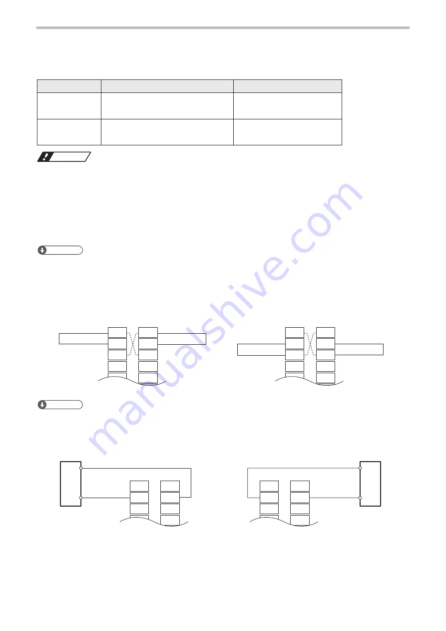
Connect IN COM. 1 (X2) and OUT COM. 1 (Y2) respectively to the power supply for input and output.
For the I/O connector terminals, connect IN COM. 2 and OUT COM. 2 respectively to the power supply in the same
manner.
Use the internal power
Use the external power
NPN connection
IN COM. 1 (X2)
- 24V OUT (X1)
IN COM. 1 (X2)
- 24V
OUT COM. 1 (Y2) - 0V OUT (Y1)
OUT COM. 1 (Y2) - 0V
PNP connection
IN COM. 1 (X2)
- 0V OUT (X3)
IN COM. 1 (X2)
- 0V
OUT COM. 1 (Y2) - 24V OUT (Y3)
OUT COM. 1 (Y2) - 24V
ワㄐㄕㄊㄆ
• Do not short-circuit 24V OUT (X1, Y3) and 0V OUT (Y1, X3). Also, do not short-circuit IN COM. 1 (X2) and OUT COM. 2
(Y2, X12). Starting the laser marker with these terminals short-circuited will cause the laser marker to malfunction.
• Do not mix up with the external and internal power supplies.
• Do not mix the NPN and PNP connecting patterns.
• When using the internal power supply (X1, X3, Y1, Y3), the total current of the power supply for the external device and
the consumption current for the I/O control should be less than 300mA.
• If you control the laser marker by the external power such as PLC, do not connect anything to the internal power 24V
OUT (X1, Y3) or 0V OUT (X3, Y1) of the I/O terminal block. If a short bar is installed, remove it.
ンㄆㄇㄆㄓㄆㄏㄆ
• IN COM. 1 and OUT COM. 1 of the I/O terminal block are independent from IN COM. 2 and OUT COM. 2 of the I/O
connector. If you use the I/O connector terminal, connect input common/output common of the I/O terminal block and the
I/O connector to power supply respectively.
To use the internal power (the I/O terminal block is not connected to an external control device)
24V OUT
IN COM. 1
0V OUT
OUT COM. 1
IN COM. 1
0V OUT
24V OUT
OUT COM. 1
X1
X2
X3
X4
X5
X6
Y1
Y2
Y3
Y4
Y5
Y6
X1
X2
X3
X4
X5
X6
Y1
Y2
Y3
Y4
Y5
Y6
I/O terminal block
I/O terminal block
NPN connection
Short-
circuited
Short-
circuited
Short-
circuited
Short-
circuited
PNP connection
ンㄆㄇㄆㄓㄆㄏㄆ
• The dotted line indicates that the terminals are connected inside of the laser marker.
To use the external power (connected to an external control device such as PLC)
IN COM. 1
OUT COM. 1
0V
24V
IN COM. 1
OUT COM. 1
0V
24V
X1
X2
X3
X4
X5
Y1
Y2
Y3
Y4
Y5
X1
X2
X3
X4
X5
Y1
Y2
Y3
Y4
Y5
I/O terminal block
I/O terminal block
NPN connection
External power
supply
External
power supply
PNP connection
ME-LPGS-SM-8
Содержание LP-GS Series
Страница 17: ...1 Product Overview ME LPGS SM 8 ...
Страница 32: ...2 Laser Marker Installation ME LPGS SM 8 ...
Страница 48: ...3 Operation Method ME LPGS SM 8 ...
Страница 68: ...4 External Control Using I O ME LPGS SM 8 ...
Страница 107: ...5 External Control by Communication Commands ME LPGS SM 8 ...
Страница 116: ...6 Link Control with External Devices ME LPGS SM 8 ...
Страница 141: ...7 Maintenance ME LPGS SM 8 ...
Страница 161: ...161 MEMO ME LPGS SM 8 ...
Страница 162: ...Troubleshooting ME LPGS SM 8 ...
Страница 186: ...Index ME LPGS SM 8 ...
Страница 188: ...188 Unit power cable 26 USB 30 45 V Vibration resistance 33 W Warning 177 Z Z axis adjustment module 154 ME LPGS SM 8 ...
Страница 189: ......
Страница 190: ... Panasonic Industrial Devices SUNX Co Ltd 2014 2019 April 2019 ...


