34
2-2 Installation Space
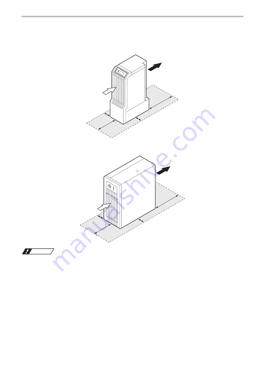
To keep the appropriate air cooling performance, provide space around the laser marker as shown in the following figure.
Head
q
w
150mm
50mm
50mm
200mm
q
Intake
w
Exhaust
Controller
150mm
50mm
50mm
200mm
q
w
q
Intake
w
Exhaust
ワㄐㄕㄊㄆ
• To maintain the air-cooling performance of the laser marker, install both the head and controller in a well-ventilated
place.
• Installing near a heating element could cause the ambient temperature exceeding the specification range, which may
cause malfunction of the product.
• When setting more than one laser marker, install them so that a space of 300 mm or more is given between the heads of
each marker. Not doing so may cause malfunction. It may cause malfunction.
ME-LPGS-SM-8
Содержание LP-GS Series
Страница 17: ...1 Product Overview ME LPGS SM 8 ...
Страница 32: ...2 Laser Marker Installation ME LPGS SM 8 ...
Страница 48: ...3 Operation Method ME LPGS SM 8 ...
Страница 68: ...4 External Control Using I O ME LPGS SM 8 ...
Страница 107: ...5 External Control by Communication Commands ME LPGS SM 8 ...
Страница 116: ...6 Link Control with External Devices ME LPGS SM 8 ...
Страница 141: ...7 Maintenance ME LPGS SM 8 ...
Страница 161: ...161 MEMO ME LPGS SM 8 ...
Страница 162: ...Troubleshooting ME LPGS SM 8 ...
Страница 186: ...Index ME LPGS SM 8 ...
Страница 188: ...188 Unit power cable 26 USB 30 45 V Vibration resistance 33 W Warning 177 Z Z axis adjustment module 154 ME LPGS SM 8 ...
Страница 189: ......
Страница 190: ... Panasonic Industrial Devices SUNX Co Ltd 2014 2019 April 2019 ...


