67
3-4-4 Remote mode settings
To control the laser marker externally using I/O or serial communication commands, set the operation mode to the remote
mode with one of the following methods.
Select the method to switch to the remote mode on the system settings screen of Laser Marker NAVI smart. Refer to “3-4-3
Settings before external control” (P.64).
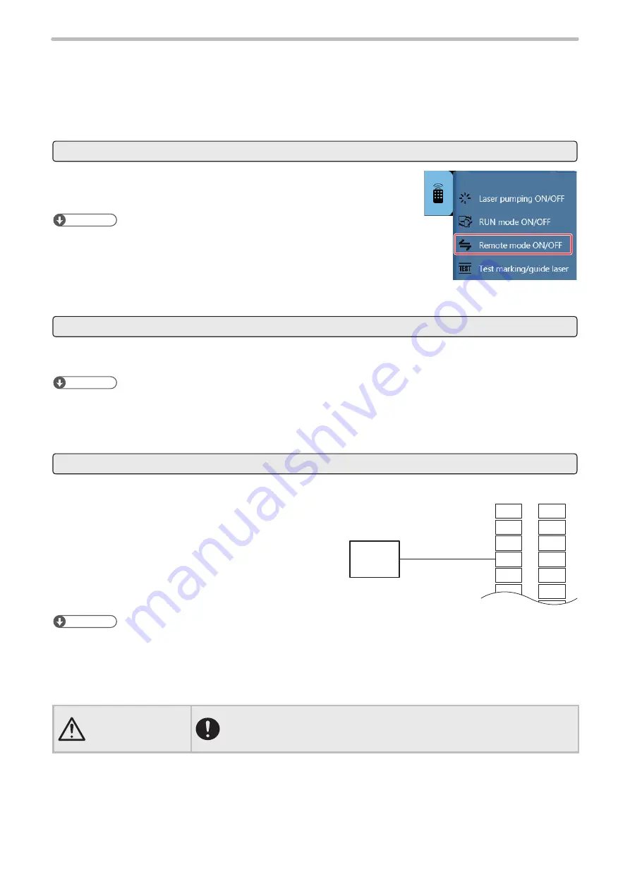
Remote mode switching by Laser Marker NAVI smart
Click the “Laser Marker Operation” tool of Laser Marker NAVI smart. Then, click
“Remote mode ON/OFF”. Click “Yes” on the confirmation screen to switch the
laser marker to the remote mode.
ンㄆㄇㄆㄓㄆㄏㄆ
• The “Remote mode ON/OFF” button is available when the following screens are
selected with the online connection established.
• Marking settings screen
• Operator settings (restricted) screen
• Monitor screen
Startup the laser marker in the remote mode (Laser Marker NAVI smart can switch the remote mode)
When you turn ON the key switch of the laser marker, the system starts in the remote mode. Use the remote mode
switch button of Laser Marker NAVI smart for releasing and resetting the remote mode.
ンㄆㄇㄆㄓㄆㄏㄆ
• If you want to start up the laser marker in the remote mode, you need to configure the settings on the system settings
screen of Laser Marker NAVI smart in advance.
• If you have configured the laser marker to start up in the remote mode, you cannot switch the remote mode from I/O.
Remote mode switching using I/O
Turn ON REMOTE IN (X4) of the I/O terminal block on the
controller.
ンㄆㄇㄆㄓㄆㄏㄆ
• To enable switching to the remote mode by REMOTE IN (X4) on the I/O terminal block, you need to configure the
settings on the system settings screen of Laser Marker NAVI smart in advance.
• If you have configured the remote mode switching method to the I/O terminal block, you cannot switch the remote mode
from the Laser Marker NAVI smart screen.
WARNING
• If the laser marker is set to enter the remote mode at startup or by I/O control,
construct a manual resetting system to re-pump the laser when the laser
pumping is turned to off due to an emergency stop or an interlock.
REMOTE IN
X1
X2
X3
X4
X5
X6
X7
Y1
Y2
Y3
Y4
Y5
Y6
Y7
PLC, etc.
OUTPUT
I/O terminal block
ME-LPGS-SM-8
Содержание LP-GS Series
Страница 17: ...1 Product Overview ME LPGS SM 8 ...
Страница 32: ...2 Laser Marker Installation ME LPGS SM 8 ...
Страница 48: ...3 Operation Method ME LPGS SM 8 ...
Страница 68: ...4 External Control Using I O ME LPGS SM 8 ...
Страница 107: ...5 External Control by Communication Commands ME LPGS SM 8 ...
Страница 116: ...6 Link Control with External Devices ME LPGS SM 8 ...
Страница 141: ...7 Maintenance ME LPGS SM 8 ...
Страница 161: ...161 MEMO ME LPGS SM 8 ...
Страница 162: ...Troubleshooting ME LPGS SM 8 ...
Страница 186: ...Index ME LPGS SM 8 ...
Страница 188: ...188 Unit power cable 26 USB 30 45 V Vibration resistance 33 W Warning 177 Z Z axis adjustment module 154 ME LPGS SM 8 ...
Страница 189: ......
Страница 190: ... Panasonic Industrial Devices SUNX Co Ltd 2014 2019 April 2019 ...


