28
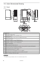
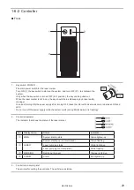
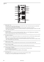
2. Signal connector: SIGNAL
This is the terminal for communicating between head and controller.
Connect the attached signal cable.
3. Power connector: POWER
This is the connector for supplying the power to the head.
Connect the attached unit power cable.
4. Frame ground terminal: F.G.
This is the terminal for ground. Ground this terminal to the earth permanently.
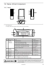
5. Laser emission port
The emission port of the marking laser and the guide laser for LP-GS051(-L).
6. Laser pointer emission port
From this port the red laser pointer radiates in oblique direction for the guide pointer function. The pointer radiates
also when using the work distance indication by the guide laser for LP-GS051(-L). Refer to “2-3-4 Marking position
check” (P.39).
To use these guide laser functions, do not seal the laser pointer emission port at the installation.
7. Head air-cooling inlet
The air-cooling inlet for the head. Fans and a filter are installed.
8. Head air-cooling outlet
The air-cooling outlet for the head.
ME-LPGS-SM-8
Содержание LP-GS Series
Страница 17: ...1 Product Overview ME LPGS SM 8 ...
Страница 32: ...2 Laser Marker Installation ME LPGS SM 8 ...
Страница 48: ...3 Operation Method ME LPGS SM 8 ...
Страница 68: ...4 External Control Using I O ME LPGS SM 8 ...
Страница 107: ...5 External Control by Communication Commands ME LPGS SM 8 ...
Страница 116: ...6 Link Control with External Devices ME LPGS SM 8 ...
Страница 141: ...7 Maintenance ME LPGS SM 8 ...
Страница 161: ...161 MEMO ME LPGS SM 8 ...
Страница 162: ...Troubleshooting ME LPGS SM 8 ...
Страница 186: ...Index ME LPGS SM 8 ...
Страница 188: ...188 Unit power cable 26 USB 30 45 V Vibration resistance 33 W Warning 177 Z Z axis adjustment module 154 ME LPGS SM 8 ...
Страница 189: ......
Страница 190: ... Panasonic Industrial Devices SUNX Co Ltd 2014 2019 April 2019 ...


