GE Multilin
745 Transformer Management Relay
8-3
8 COMMISSIONING
8.1 GENERAL
8
8.1.5 TEST EQUIPMENT
It is possible to completely verify the 745 relay operation using the built-in test and simulation features described earlier in
this manual. However, some customers prefer to perform simple signal-injection tests to verify the basic operation of each
element placed into service. The procedures described in this chapter have been designed for this purpose. To use the
built-in facilities, refer to the appropriate sections in this manual.
The conventional, decades-old approach to testing relays utilized adjustable voltage and current sources, variacs, phase
shifters, multimeters, timing device, and the like. In the last few years several instrumentation companies have offered
sophisticated instrumentation to test protective relays. Generally this equipment offers built-in sources of AC voltage and
current, DC voltage and current, timing circuit, variable frequency, phase shifting, harmonic generation, and complex fault
simulation. If using such a test set, refer to the equipment manufacturer's instructions to generate the appropriate signals
required by the procedures in this section. If you do not have a sophisticated test set, then you will need the following "con-
ventional" equipment:
•
Variable current source able to supply up to 40 A (depends on relay settings)
•
Variable power resistors to control current amplitude
•
Ten-turn 2 K
Ω
low-power potentiometer
•
Power rectifier to build a circuit to generate 2nd harmonics
•
Accurate timing device
•
Double-pole single-throw contactor suitable for at least 40 amperes AC.
•
Combined fundamental and 5th-harmonic adjustable current supply for elements involving the 5
th
harmonic.
•
Variable-frequency source of current or voltage to test over/underfrequency and frequency trend elements.
•
Ammeters (RMS-responding), multimeters, voltmeters
•
variable DC mA source
•
variable DC mV source
•
single-pole single-throw contactor
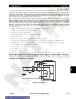
The simple test setup shown below can be used for the majority of tests. When the diode is not shorted and the two cur-
rents are summed together prior to the switch, the composite current contains the 2
nd
harmonic necessary to verify the 2
nd
harmonic restraint of the harmonic restraint percent differential elements. With the diode shorted and the two currents fed to
separate relay inputs, the slope of the differential elements can be measured. With only
I
1
connected (with a return path)
the pickup level of any element can be measured.
Figure 8–1: TEST SETUP
Содержание TRANSFORMER MANAGEMENT RELAY 745
Страница 2: ...Courtesy of NationalSwitchgear com ...

