6-16
745 Transformer Management Relay
GE Multilin
6.4 A3 EVENT RECORDER
6 ACTUAL VALUES
6
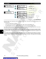
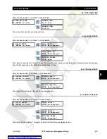
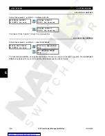
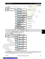
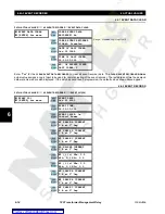
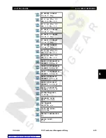
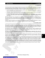
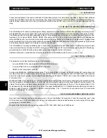
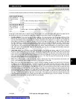
The 745 event recording feature runs continuously, capturing and storing the conditions present at the moment of occur-
rence of the last 128 events, as well as the time and date of each event. The header message for each event contains two
pieces of information: the event number (higher numbers denote more recent events) and the event date. If the event
record is clear or if the date has never been programmed, “Unavailable” is displayed instead of a date. No more than 128
events are stored at the same time.
The recorded event displayed for Logic inputs, Virtual Inputs, and Relay outputs will show the programmed name of
the input/output.
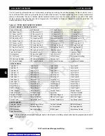
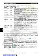
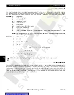
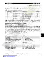
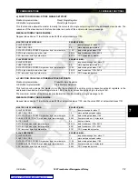
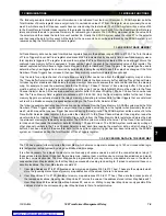
Table 6–1: TYPES AND CAUSES OF EVENTS
PICKUP / OPERATE / DROPOUT EVENTS
Percent Differential
Inst Differential
W1 Phase Time OC
W2 Phase Time OC
W3 Phase Time OC
W1 Phase Inst OC 1
W2 Phase Inst OC 1
W3 Phase Inst OC 1
W1 Phase Inst OC 2
W2 Phase Inst OC 2
W3 Phase Inst OC 2
W1 Neutral Time OC
W2 Neutral Time OC
W3 Neutral Time OC
W1 Neutral Inst OC 1
W2 Neutral Inst OC 1
W3 Neutral Inst OC 1
W1 Neutral Inst OC 2
W2 Neutral Inst OC 2
W3 Neutral Inst OC 2
W1 Ground Time OC
W2 Ground Time OC
W3 Ground Time OC
W1 Ground Inst OC 1
W2 Ground Inst OC 1
W3 Ground Inst OC 1
W1 Ground Inst OC 2
W2 Ground Inst OC 2
W3 Ground Inst OC 2
W1 Restd Gnd Fault
W2 Restd Gnd Fault
W3 Restd Gnd Fault
W1 Neg Seq Time OC
W2 Neg Seq Time OC
W3 Neg Seq Time OC
W1 Neg Seq Inst OC
W2 Neg Seq Inst OC
W3 Neg Seq Inst OC
Underfrequency 1
Underfrequency 2
Frequency Decay 1
Frequency Decay 2
Frequency Decay 3
Frequency Decay 4
Overfrequency
5th Harmonic Level
Volts-Per-Hertz 1
Volts-Per-Hertz 2
W1 THD Level
W2 THD Level
W3 THD Level
W1 Harmonic Derating
W2 Harmonic Derating
W3 Harmonic Derating
Analog Level 1
Analog Level 2
W1 Current Demand
W2 Current Demand
W3 Current Demand
Transformer Overload
ON/OFF EVENTS
Logic Input 1
Logic Input 2
Logic Input 3
Logic Input 4
Logic Input 5
Logic Input 6
Logic Input 7
Logic Input 8
Logic Input 9
Logic Input 10
Logic Input 11
Logic Input 12
Logic Input 13
Logic Input 14
Logic Input 15
Logic Input 16
Virtual Input 1
Virtual Input 2
Virtual Input 3
Virtual Input 4
Virtual Input 5
Virtual Input 6
Virtual Input 7
Virtual Input 8
Virtual Input 9
Virtual Input 10
Virtual Input 11
Virtual Input 12
Virtual Input 13
Virtual Input 14
Virtual Input 15
Virtual Input 16
Output Relay 1
Output Relay 2
Output Relay 3
Output Relay 4
Output Relay 5
Output Relay 6
Output Relay 7
Output Relay 8
Self-Test Relay
Virtual Output 1
Virtual Output 2
Virtual Output 3
Virtual Output 4
Virtual Output 5
Setpoint Group 1
Setpoint Group 2
Setpoint Group 3
Setpoint Group 4
Test Mode
Simulation Disabled
Simulation Prefault
Simulation Fault
Simulation Playback
Logic Input Reset
Front Panel Reset
Comm Port Reset
Manual Trace Trigger
Auto Trace Trigger
Control Power
Aging factor Limit
Ambient Temperature
Tap Changer failure
ERROR! EVENTS
Logic Input Power
Analog Output Power
Unit Not Calibrated
EEPROM Memory
Real-Time Clock
Emulation Software
Int. Temperature
FlexLogic Equation
DSP Processor
Bad Xfmr Settings
IRIG-B Signal
Setpt Access Denied
Ambnt temperature
NOTE
Содержание TRANSFORMER MANAGEMENT RELAY 745
Страница 2: ...Courtesy of NationalSwitchgear com ...

