5-4
745 Transformer Management Relay
GE Multilin
5.1 OVERVIEW
5 SETPOINTS
5
5.1.2 SETPOINT ENTRY
Prior to commissioning the 745 relay, setpoints defining transformer characteristics, inputs, output relays, and protection
settings must be entered, via one of the following methods:
•
Front panel, using the keypad and display.
•
Front RS232 or rear terminal RS485/RS422 communication ports, and a portable computer running the 745PC soft-
ware or a SCADA system running user-written software.
Any of these methods can be used to enter the same information. A computer, however, makes entry much easier. Files
can be stored and downloaded for fast, error free entry when a computer is used. Settings files can be prepared and stored
on disk without the need to connect to a relay.
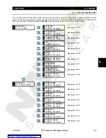
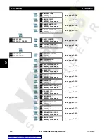
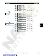
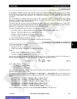
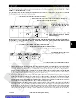
All setpoint messages are illustrated and described in blocks throughout this chapter.
The 745 relay leaves the factory with
setpoints programmed to default values, and it is these values that are shown in all the setpoint message illustrations.
Some of these factory default values can be left unchanged.
There are many 745 setpoints that must be entered for the relay to function correctly. In order to safeguard against installa-
tion when these setpoints have not been entered, the 745 does not allow signaling of any output relay. In addition, the In
Service LED is off and the Self-Test Error LED on until the
S1 745 SETUP
ÖØ
INSTALLATION
Ö
745 SETPOINTS
value is set to
“Programmed”. This setpoint is defaulted to Not Programmed when the relay leaves the factory. The
SETPOINTS HAVE NOT
BEEN PROGRAMMED
diagnostic message appears until the 745 is put in the programmed state:
Messages may vary somewhat from those illustrated because of installed options. Also, some messages associated with
disabled features (or optional features which have not been ordered) are hidden.
These messages are shown with a
shaded message box.
•
KEYPAD ENTRY
: See Section 2.1: Using the Front Panel Display on page 2–1 for details on maneuvering through the
messages, viewing actual values, and changing setpoints.
•
COMPUTER ENTRY
: Setpoint values are grouped together on a screen in the 745PC software. The data is organized
in a system of menus. See Section 4.2: 745PC Software Interface on page 4–5 for details.
•
SCADA ENTRY
: Details of the complete communication protocol for reading and writing setpoints are given in Chap-
ters 8 and 9. A programmable SCADA system connected to the RS485/RS422 terminals can make use of communica-
tion commands for remote setpoint programming, monitoring, and control.
5.1.3 SETPOINT WRITE ACCESS
The 745 design incorporates hardware and passcode security features to provide protection against unauthorized setpoint
changes.
A hardware jumper must be installed across the setpoint access terminals on the back of the relay to program new set-
points using the front panel keys. When setpoint programming is via a computer connected to the communication ports, no
setpoint access jumper is required.
Passcode protection may also be enabled. When enabled, the 745 requests a numeric passcode before any setpoint can
be entered. As an additional safety measure, a minor self-test error is generated when the passcode is entered incorrectly
three times in a row.
Содержание TRANSFORMER MANAGEMENT RELAY 745
Страница 2: ...Courtesy of NationalSwitchgear com ...


