7-44
745 Transformer Management Relay
GE Multilin
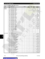
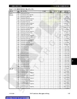
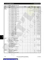
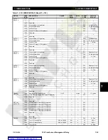
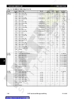
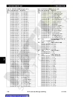
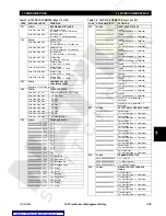
7.4 MODBUS MEMORY MAP
7 COMMUNICATIONS
7
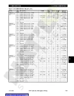
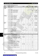
VOLTS-PER-
HERTZ 2
2310
Volts-Per-Hertz 2 Function
---
---
---
F30
0 = Disabled
2311
Volts-Per-Hertz 2 Target
---
---
---
F46
1 = Latched
2312
Volts-Per-Hertz 2 Min. Operating Voltage
0.10 to 0.99
0.01
x VT
F3
10 = 0.10 x VT
2313
Volts-Per-Hertz 2 Pickup
1.00 to 4.00
0.01
V/Hz
F3
214 = 2.14 V/Hz
2314
Volts-Per-Hertz 2 Shape
---
---
---
F86
0 = Def. Time
2315
Volts-Per-Hertz 2 Delay
0.00 to 600.00
0.01
s
F3
4500 = 45.00 s
2316
Volts-Per-Hertz 2 Reset
0.0 to 6000.0
0.1
s
F2
0.0 s
2317
Volts-Per-Hertz 2 Block
---
---
---
F87
0 = Disabled
2318
Reserved
↓
↓
↓
↓
↓
↓
↓
231F
Reserved
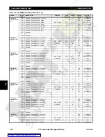
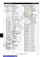
WINDING 1
THD LEVEL
2320
Winding 1 THD Level Function
---
---
---
F30
0 = Disabled
2321
Winding 1 THD Level Target
---
---
---
F46
0 = Self-reset
2322
Winding 1 THD Level Min. Operating Current
0.03 to 1.00
0.01
×
CT
F3
10 = 0.10
×
CT
2323
Winding 1 THD Level Pickup
0.1 to 50.0
0.1
% ƒo
F2
500 = 50.0%
2324
Winding 1 THD Level Delay
0 to 60000
1
s
F1
10 s
2325
Winding 1 THD Level Block
---
---
---
F87
0 = Disabled
2326
Reserved
↓
↓
↓
↓
↓
↓
↓
232F
Reserved
WINDING 2
THD LEVEL
2330
Winding 2 THD Level Function
---
---
---
F30
0 = Disabled
2331
Winding 2 THD Level Target
---
---
---
F46
0 = Self-reset
2332
Winding 2 THD Level Min. Operating Current
0.03 to 1.00
0.01
×
CT
F3
10 = 0.10
×
CT
2333
Winding 2 THD Level Pickup
0.1 to 50.0
0.1
% ƒo
F2
500 = 50.0%
2334
Winding 2 THD Level Delay
0 to 60000
1
s
F1
10 s
2335
Winding 2 THD Level Block
---
---
---
F87
0 = Disabled
2336
Reserved
↓
↓
↓
↓
↓
↓
↓
233F
Reserved
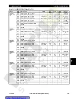
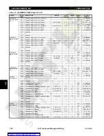
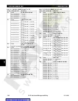
WINDING 3
THD LEVEL
2340
Winding 3 THD Level Function
---
---
---
F30
0 = Disabled
2341
Winding 3 THD Level Target
---
---
---
F46
0 = Self-reset
2342
Winding 3 THD Level Min. Operating Current
0.03 to 1.00
0.01
×
CT
F3
10 = 0.10
×
CT
2343
Winding 3 THD Level Pickup
0.1 to 50.0
0.1
% ƒo
F2
500 = 50.0%
2344
Winding 3 THD Level Delay
0 to 60000
1
s
F1
10 s
2345
Winding 3 THD Level Block
---
---
---
F87
0 = Disabled
2346
Reserved
↓
↓
↓
↓
↓
↓
↓
234F
Reserved
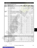
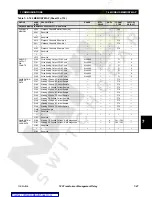
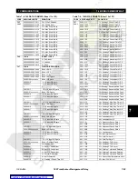
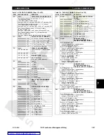
WINDING 1
HARMONIC
DERATING
2350
Winding 1 Harm Derating Function
---
---
---
F30
0 = Disabled
2351
Winding 1 Harm Derating Target
---
---
---
F46
0 = Self-reset
2352
Winding 1 Harm Derating Min. Operating Current
0.03 to 1.00
0.01
×
CT
F3
10 = 0.10
×
CT
2353
Winding 1 Harm Derating Pickup
0.01 to 0.98
0.01
---
F3
90 = 0.90
2354
Winding 1 Harm Derating Delay
0 to 60000
1
s
F1
10 s
2355
Winding 1 Harm Derating Block
---
---
---
F87
0 = Disabled
2356
Reserved
↓
↓
↓
↓
↓
↓
↓
235F
Reserved
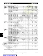
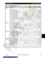
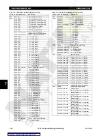
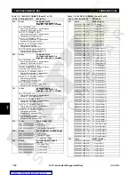
WINDING 2
HARMONIC
DERATING
2360
Winding 2 Harm Derating Function
---
---
---
F30
0 = Disabled
2361
Winding 2 Harm Derating Target
---
---
---
F46
0 = Self-reset
2362
Winding 2 Harm Derating Min. Operating Current
0.03 to 1.00
0.01
×
CT
F3
10 = 0.10
×
CT
2363
Winding 2 Harm Derating Pickup
0.01 to 0.98
0.01
---
F3
90 = 0.90
2364
Winding 2 Harm Derating Delay
0 to 60000
1
s
F1
10 s
2365
Winding 2 Harm Derating Block
---
---
---
F87
0 = Disabled
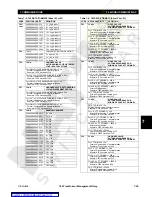
Table 7–5: 745 MEMORY MAP (Sheet 32 of 35)
GROUP
ADDR
(HEX)
DESCRIPTION
RANGE
STEP
VALUE
UNITS
FORMAT
CODE
FACTORY
DEFAULT
Содержание TRANSFORMER MANAGEMENT RELAY 745
Страница 2: ...Courtesy of NationalSwitchgear com ...

