7-68
745 Transformer Management Relay
GE Multilin
7.5 DNP COMMUNICATIONS
7 COMMUNICATIONS
7
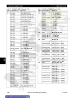
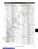
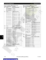
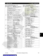
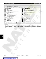
Table Notes:
1.
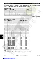
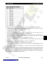
Unless otherwise specified, an event object will be generated for a point if the current value of the point changes by an
amount greater than or equal to two percent of its previous value.
2.
An event object is created for these points if the current value of a point is in any way changed from its previous value.
3.
An event object is created for the System Frequency point if the system frequency changes by 0.04 Hz or more from its
previous value.
4.
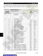
The data returned by a read of the User Map Value points is determined by the values programmed into the corre-
sponding User Map Address registers (which are only accessible via Modbus). Refer to the section titled "Accessing
Data Via The User Map" in this chapter for more information. Changes in User Map Value points never generate event
objects. Because of the programmable nature of the user map, it cannot be determined at read time if the source value
is signed or unsigned. For this reason, the data returned in a 32-bit variation is never sign-extended even if the source
value is negative.
5.
Depending upon the configuration and/or programming of the 745, this value may not be available. Should this be the
case, a value of zero will be returned.
6.
Points with format F78 and F93 are scaled based upon the value of the
WINDING 1 PHASE CT PRIMARY
setpoint (Point
0). It is necessary to read Point 0 and refer to the descriptions of these formats (see Table 7–6: 745 Data Formats on
page 7–48) in order to determine the scale factor.
7.
As for Note 6, except the affected formats are F79 and F94 and the scaling is determined by the value from Point 1.
8.
As for Note 6 except the affected formats are F80 and F95 and the scaling is determined by the value from Point 2.
9.
As for Note 6 except the affected format is F81 and the scaling is determined by the value read from Point 3.
10. As for Note 6 except the affected format is F82 and the scaling is determined by the value read from Point 4.
11. As for Note 6 except the affected format is F83 and the scaling is determined by the value read from Point 5.
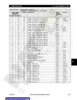
12. The “Total Accumulated Loss Of Life” is a 32-bit, unsigned, positive value. As a consequence, a master performing 16-
bit reads cannot be guaranteed to be able to read this point under all conditions. When this point's value exceeds
65535 (0xFFFF hex), a 16-bit read will return 0xFFFF (hex) and the over-range bit in the flag returned with the data will
be set. Because of this possibility of over-range, the default variation for this object is 2 (that is, 16-bit analog input with
flag).
13. There are two defined maps for Analog Output points. The map used is specified by the setting of the "Point Mapping"
setpoint at Modbus address 10D1 (hex). This setpoint may be set to a value of "Disabled" or "Enabled". When "Dis-
abled", only the preassigned Analog Output points are available at indices 0 through 72.
When "Enabled", the User Map Values are assigned to points 0 through 119 with the preassigned Analog Outputs following
beginning with point index 120. The value read from points 0 through 119 will depend upon the value programmed into the
corresponding User Map Address setpoint (note that programming of these setpoints can only be accomplished via Mod-
bus). Refer to the section in this chapter titled Accessing Data Via The User Map for more information.
Please note that changes in User Map Values never generate event objects.
Содержание TRANSFORMER MANAGEMENT RELAY 745
Страница 2: ...Courtesy of NationalSwitchgear com ...

