GE Multilin
745 Transformer Management Relay
7-11
7 COMMUNICATIONS
7.3 MODBUS FUNCTIONS
7
3.
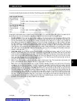
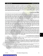
Setpoints may be written via the user map. In the example above, to change the value of Restrained Differential Pickup
to 0.20 x CT through the user map, transmit the following Modbus message:
7.3.6 FUNCTION CODE SUBSTITUTIONS
Most 745 supported Modbus commands can be performed via function codes 03h (or 04h), and 10h and special memory
map addresses.
a) FUNCTION CODES 03H AND 04H SUBSTITUTIONS
Function codes 03h and 04h are interchangeable. Both have identical message formats, and both perform the same action.
b) FUNCTION CODE 05H SUBSTITUTION
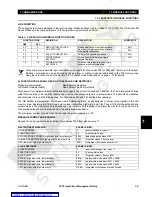
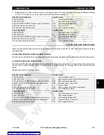
Function code 05h (Execute Operation) can be performed by writing the command as if it were data in the memory map.
For example, to write operation code 01h (reset targets) to register 0080h, the message format and example is shown
below.
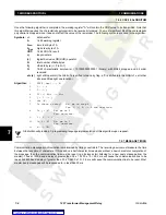
Request slave device 11 to reset targets:
MASTER QUERY MESSAGE:
EXAMPLE (HEX):
SLAVE ADDRESS
11
query message for slave 11
FUNCTION CODE
06
store single setpoint values
DATA STARTING ADDRESS: high order byte, low order byte
01 85
data starting at address 0185
DATA: high order byte, low order byte
00 14
0014 = 0.30
×
I
d
CRC: low order byte, high order byte
9B 40
CRC computed by master
SLAVE RESPONSE:
EXAMPLE (HEX):
SLAVE ADDRESS
11
response message from slave 11
FUNCTION CODE
06
store single setpoint values
DATA STARTING ADDRESS: high order byte, low order byte
01 85
data starting at address 0185
DATA: high order byte, low order byte
00 14
0014 = 0.30
×
I
d
CRC: low order byte, high order byte
9B 40
CRC computed by slave
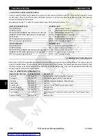
MASTER QUERY MESSAGE:
EXAMPLE (HEX):
SLAVE ADDRESS
11
query message for slave 11
FUNCTION CODE
10
store multiple setpoints (substituted for code 05H)
DATA STARTING ADDRESS: high order byte, low order byte
00 80
data starting at address 0080
NUMBER OF SETPOINTS: high order byte, low order byte
00 01
1 register values = 2 bytes total
BYTE COUNT
02
2 bytes of data
DATA: high order byte, low order byte
00 01
0001 = operation code 0001H (reset targets)
CRC: low order byte, high order byte
B5 90
CRC computed by master
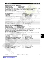
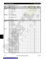
SLAVE RESPONSE:
EXAMPLE (HEX):
SLAVE ADDRESS
11
response message from slave 11
FUNCTION CODE
10
store multiple setpoints
DATA STARTING ADDRESS: high order byte, low order byte
00 80
data starting at address 0080
NUMBER OF SETPOINTS: high order byte, low order byte
00 01
1 setpoint values = 2 bytes total
CRC: low order byte, high order byte
02 31
CRC computed by slave
Содержание TRANSFORMER MANAGEMENT RELAY 745
Страница 2: ...Courtesy of NationalSwitchgear com ...

