GE Multilin
745 Transformer Management Relay
8-9
8 COMMISSIONING
8.4 DISPLAY, METERING, COMMUNICATIONS, AND ANALOG OUTPUTS
8
(EQ 8.7)
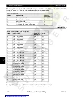
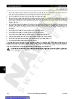
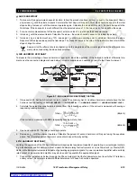
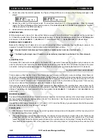
By injecting a current into Phase A of Winding 1 and Phase A of Winding 2 only,
I
W1b
=
I
W1c
= 0 A. Therefore, if we assume
an injected current of 1
×
CT, the
transformed
Y-side currents will be:
(EQ 8.8)
For the purposes of the differential elements only
, the transformation has reduced the current to 0.57 times its original value
into Phase A, and created an apparent current into Phase B, for the described injection condition. If a 1
×
CT is now
injected into Winding 1 Phase A, the following values for the differential currents for all three phases should be obtained:
Phase A differential: 0.57
×
CT
∠
0° Lag
Phase B differential: 0.57
×
CT
∠
180° Lag
Phase C: 0
×
CT.
b) EFFECTS OF ZERO-SEQUENCE COMPENSATION REMOVAL
The transformation used to obtain the 30° phase shift on the Y-side automatically removes the zero-
sequence current from those signals. The 745 always removes the zero-sequence current from the delta
winding currents.
If the zero-sequence component is removed from the Delta-side winding currents, the Winding 2 current values will change
under unbalanced conditions. Consider the case described above, with the 1
×
CT injected into Phase A of Winding 2.
For the 1
×
CT current, the zero-sequence value is 1/3 of 1.0
×
CT or 0.333
×
CT A. The value for
I
W2a'
is therefore (1.0 –
0.333)
×
CT = 0.6667
×
CT A. This value must be divided by the CT error correction factor of 0.797 as described above.
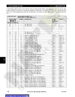
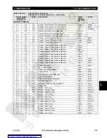
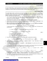
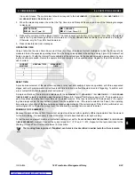
Therefore, the value of differential current for Phase A, when injecting 1
×
CT in Winding 2 only, is:
(EQ 8.9)
The action of removing the zero-sequence current results in a current equal to the zero-sequence value introduced into
phases B and C. Hence, the differential current for these two elements is:
(EQ 8.10)
Now, applying 1
×
CT into Winding 1 Phase A and the same current into Phase A Winding 2, but 180° out-of- phase to prop-
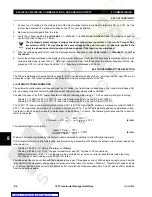
erly represent CT connections, the total differential current in the Phase A element will be (0.57 – 0.84)
×
CT = –0.26
×
CT.
The injection of currents into Phase A of Windings 1 and 2 in this manner introduces a differential current of (–0.57
×
CT +
0.42
×
CT) = –0.15
×
CT into Phase B and (0.0
×
CT + 0.42
×
CT) = 0.42
×
CT into Phase C.
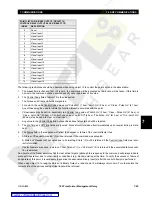
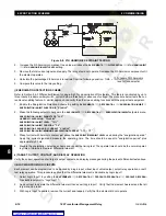
8.4.5 AMBIENT TEMPERATURE INPUT
a) BASIC CALIBRATION OF RTD INPUT
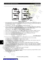
1.
Enable ambient temperature sensing with the
S2 SYSTEM SETUP
ÖØ
AMBIENT TEMP
Ö
AMBIENT TEMPERATURE SENSING
setpoint.
2.
Connect a thermocouple to the relay terminals B10, B11, and B12 and read through the
A2 METERING
ÖØ
AMBIENT
TEMP
Ö
AMBIENT TEMPERATURE
actual value.
3.
Compare the displayed value of temperature against known temperature at the location of the sensor. Use a thermom-
eter or other means of obtaining actual temperature.
An alternative approach is to perform a more detailed calibration per the procedure outlined below.
I
W
1
a
′
I
W
1
a
I
W
1
c
–
3
-----------------------------
,
I
W
1
b
′
I
W
1
b
I
W
1
a
–
3
-----------------------------
,
I
W
1
c
′
I
W
1
c
I
W
1
b
–
3
-----------------------------
=
=
=
I
W
1
a
′
1 CT
×
3
-----------------
,
I
W
1
b
′
1 CT
×
–
3
--------------------
,
I
W
1
c
′
0 CT
×
3
-----------------
=
=
=
NOTE
I
A differential
(
)
0.667 CT A
×
0.797
-----------------------------------
0.84 CT A
×
=
=
I
B differential
(
)
I
C differential
(
)
0.333 CT A
×
0.797
-----------------------------------
0.84 CT A
×
=
=
=
Содержание TRANSFORMER MANAGEMENT RELAY 745
Страница 2: ...Courtesy of NationalSwitchgear com ...


