GE Multilin
745 Transformer Management Relay
4-3
4 HUMAN INTERFACES
4.1 HARDWARE INTERFACE
4
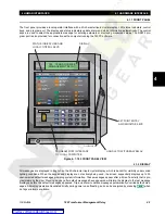
b) SYSTEM STATUS INDICATORS
TRANSFORMER DE-ENERGIZED:
The Transformer De-Energized LED indicator is on when the energization inhibit feature has
detected that the transformer is de-energized. The indicator is on if the
S4 ELEMENTS
ÖØ
DIF-
FERENTIAL
ÖØ
ENERGIZATN INHIBIT
feature is detecting the transformer as de-energized
TRANSFORMER OVERLOAD:
The Transformer Overload LED indicator is on when
S4 ELEMENTS
ÖØ
XFORMER OVERLOAD
has operated.
LOAD-LIMIT REDUCED:
The Load-Limit Reduced LED indicator is on when the adaptive harmonic factor correction fea-
ture is detecting enough harmonic content to reduce the load rating of the transformer. The
indicator is on if
S2 SYSTEM SETUP
ÖØ
HARMONICS
Ö
HARMONIC DERATING ESTIMATION
is
"Enabled" and the harmonic derating function is below 0.96.
SETPOINT GROUP 1 TO SETPOINT GROUP 4:
These indicators reflect the currently active setpoint group. The indicators flash when the cor-
responding setpoint group is being edited.
c) CONDITION INDICATORS
TRIP:
The Trip LED is on when any output relay selected to be of the
Trip
type has operated.
ALARM:
The Alarm LED is on when any output relay selected to be of the
Alarm
type has operated.
PICKUP:
The Pickup LED is on when any element has picked up. With this indicator on, the front panel
display is sequentially displaying information about each element that has picked up.
PHASE A (B OR C):
The Phase A(C) LED is on when Phase A(C) is involved in the condition detected by any ele-
ment that has picked up, operated, or is now in a latched state waiting to be reset.
GROUND:
The Ground LED is on when ground is involved in the condition detected by any element that
has picked up, operated, or is now in a latched state waiting to be reset.
4.1.5 PROGRAM PORT
Use the front panel program port for RS232 communications with the 745. As described in Section 3.2.16: RS232 Front
Panel Program Port on page 3–13, all that is required is a connection between the relay and a computer running 745PC.
For continuous monitoring of multiple relays, use the COM1 RS485/RS422 port or the COM2 RS485 port.
4.1.6 KEYPAD
a) SETPOINT KEY
Setpoints are arranged into groups of related messages called setpoint pages. Each time
is pressed, the display
advances to the first message of the next setpoints page. Pressing
while in the middle of a setpoints page advances
the display to the beginning of the next setpoint page. Pressing
while in the middle of an actual values page returns
the display to the last setpoint message viewed. If the display has timed out to the default messages, pressing
returns the display to the last viewed setpoint message. The
/
keys move between messages within a
page.
SETPOINT
SETPOINT
SETPOINT
SETPOINT
MESSAGE
MESSAGE
Содержание TRANSFORMER MANAGEMENT RELAY 745
Страница 2: ...Courtesy of NationalSwitchgear com ...

