GE Multilin
745 Transformer Management Relay
7-9
7 COMMUNICATIONS
7.3 MODBUS FUNCTIONS
7
The following example illustrates how information can be retrieved from the Event Recorder. A SCADA system polls the
Total Number of Events register once every minute. It now reads a value of 27 from the register when previously the value
was 24, which means that three new events have occurred during the last minute. The SCADA system writes a value of 25
to the Event Record Selector Index register. It then reads the data for event number 25 from the Event Recorder Data reg-
isters and stores the data to permanent memory for retrieval by an operator. The SCADA system now writes the value 26 to
the selector and then reads the data for event number 26. Finally, the SCADA system writes the value 27 to the selector
and then reads the data for this event. All the data for the new events has now been retrieved by the SCADA system, so it
resumes polling the Total Number of Events register.
7.3.4 READING TRACE MEMORY
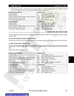
All Trace Memory data can be read from Modbus registers found in the address range 4000h to 47FFh. The 'Total Number
of Trace Triggers Since Last Clear' register at address 4004h is incremented by one every time a new trace memory wave-
form capture is triggered. The register is cleared to zero when the Trace Memory is cleared. When a new trigger occurs, the
captured trace memory buffer is assigned a 'trigger number' which is equal to the incremented value of this register. The
newest captured buffer will have a trigger number equal to the Total Number of Trace Triggers. This register can be used to
determine if any new triggers have occurred by periodically reading the register to see if the value has changed. If the Total
Number of Trace Triggers has increased, then new trace memory waveform captures have occurred.
Only the data for a single channel of a single trace memory buffer can be read from the Modbus memory map at a time.
The 'Trace Buffer Selector Index' register at address 4005h selects the trace memory buffer, and the 'Trace Channel Selec-
tor Index' register at address 4006h selects the trace memory channel, whose waveform data can be read from the memory
map. For example, to read the waveform data for the 'Winding 1 Phase C Current' of trace memory buffer 5, the value 5
must be written to the Trace Buffer Selector Index, and the value 2 (as per data format F65) must be written to the Trace
Channel Selector Index. All the captured waveform data for buffer 5, channel 'Winding 1 Phase C Current' can now be read
from the 'Trace Memory Data' registers at addresses 4010h to 4416h. Only the trace memory buffers for the last 3 trace
memory triggers are actually stored in the relay's memory. Attempting to retrieve data for older triggers that are not stored
will result in a Modbus exception response when writing to the 'Trace Buffer Selector Index'.
The following example illustrates how information can be retrieved from the Trace Memory. A SCADA system polls the Total
Number of Trace Triggers register once every minute. It now reads a value of 6 from the register when previously the value
was 5, which means that one new trigger has occurred during the last minute. The SCADA system writes a value of 6 to the
Trace Buffer Selector Index register. It then writes the value of 0 to the Trace Channel Selector Index register, reads the
waveform data for Winding 1 Phase A Current of trace buffer 6 from the Trace Memory Data registers and stores the data
to permanent memory for retrieval by an operator. The SCADA system now writes the value 1 to the Trace Channel Selec-
tor Index and then reads the waveform data for Winding 1 Phase B Current. The SCADA system continues by writing all
other channel numbers to the Trace Channel Selector Index, each time reading the waveform data, until all channels for
buffer 6 have been read. All the waveform data for the new trace memory trigger has now been retrieved by the SCADA
system, so it resumes polling the Total Number of Trace Triggers register.
7.3.5 ACCESSING DATA VIA THE USER MAP
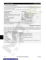
The 745 has a powerful feature, called the User Map, which allows a computer to access up to 120 non-consecutive regis-
ters (setpoints or actual values) by using one Modbus read message.
It is often necessary for a master computer to continuously poll various values in each of the connected slave relays. If
these values are scattered throughout the memory map, reading them would require numerous transmissions and would
labor the communication link. The User Map can be programmed to join any memory map address to one in the block of
consecutive User Map locations, so that they can be accessed by reading (and writing to, if joined to setpoints) these con-
secutive locations. The User Map feature consists of:
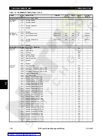
1.
User Map Addresses #1 to #120 (located at memory map addresses 0180 to 01F7 hex). These are the setpoints which
store the (possibly discontinuous) memory map addresses of the values that are to be accessed.
2.
User Map Values #1 to #120 (located at memory map addresses 0100 to 0177 hex). These are the access points of
the remapped locations. Reading User Map Value #1 returns the value at the address stored in User Map Address #1,
User Map Value #2 the value at User Map Address #2, and so on. Writing to any User Map Value is only possible if the
address stored in the corresponding User Map Address is that of a setpoint value.
Содержание TRANSFORMER MANAGEMENT RELAY 745
Страница 2: ...Courtesy of NationalSwitchgear com ...


