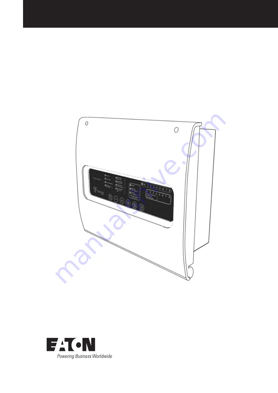
BiWire Flexi
BiWire Flexi Fire Panel
EFBW8ZONE-FLEXI / EFBW4ZONE-FLEXI / EFBW2ZONEFLEXI
Installation Manual
www.acornfiresecurity.com
Страница 1: ...BiWire Flexi BiWire Flexi Fire Panel EFBW8ZONE FLEXI EFBW4ZONE FLEXI EFBW2ZONEFLEXI Installation Manual www acornfiresecurity com www acornfiresecurity com...
Страница 2: ...E 12 Fire Protection Equipment FPE 12 Zonal Relay Contacts 12 3 INSTALLATION INSTRUCTIONS 13 3 1 Before You Begin 13 3 2 Cabling Routing Device Installation 13 3 3 Panel Installation 14 Mounting the P...
Страница 3: ...tion Buttons 26 6 2 Silence Fire Alarm Devices 26 6 3 Sound Fire Alarm Devices 26 6 4 Reset System 26 6 5 Mute Buzzer 27 6 6 Enable Disable 27 6 7 Individual Zone Test 28 6 8 Lamp Test 28 6 9 Self Tes...
Страница 4: ...m The installation of this system can only be carried out by a competent person with relevant current training and experience with access to requisite tools equipment and information as stipulated by...
Страница 5: ...ectors and manual call points and 20 output devices connected via a single 2 core screened cable The Fire Panel is available to support 4 conventional sounder circuits see technical specification for...
Страница 6: ...r the zone mode setting A maximum of 32 inputs devices detectors and or manual call points and 20 output devices is possible as one BiWire configuration example a loading calculator is available to as...
Страница 7: ...cation of power supply Further technical data for the PSE can be found in section 7 2 Note that the charging circuit will be in its high impedance state approximately 3V DC if no batteries faulty batt...
Страница 8: ...e must have the intelligent end of line module EOLM 1 fitted to continually monitor each zone for the presence of fault conditions such as detector head removal open or short circuit and for end of li...
Страница 9: ...call points devices are wired into the barrier with a 5K1 EOLR embedded in the last device Standard conventional and BiWire detection and alarm devices cannot be wired onto an intrinsically safe conv...
Страница 10: ...W Battery impedance fault Charger Fault ON ON ON SLOW Charger voltage fault Sounder Fault ON ON SLOW SLOW Short or Open circuit condition on the sounder circuit FRE Fault ON ON SLOW SLOW Short or Open...
Страница 11: ...perated by an external volt free contact A short circuit at this terminal will activate non latching sounders no indication will show on the fire alarm panel The sounders will automatically silence wh...
Страница 12: ...terlink Relay in conjunction with a non latching zone can be used to link two BiWire Flexi fire panels together Figure 12 or to link a BiWire Flexi to a BiWire Ultra panel It is recommended to use a n...
Страница 13: ...g sounder circuits apply 8 BiWire Zones 0 Sounder Outputs Available 1 4 Conventional Zones 2 Sounder Outputs Available 5 8 Conventional Zones 4 Sounder Outputs Available Each sounder circuit must be t...
Страница 14: ...MPT TO INSTALL THIS EQUIPMENT UNTIL YOU HAVE FULLY READ AND UNDERSTOOD THE OPERATION AS DESCRIBED WITHIN THIS MANUAL FAILURE TO DO SO MAY RESULT IN DAMAGE TO THE EQUIPMENT AND COULD INVALIDATE YOUR WA...
Страница 15: ...LLY ON THE PERIMETER OF A BUILDING NEAR A PERMANENT ENTRANCE Mounting the Panel To remove the front cover of the panel unscrew the two retraining screws located at the top corners of the panel see Fig...
Страница 16: ...Fit the glands to the back box and pull through the required cables Using the mounting holes in the back box drill holes into the wall and insert wall plugs and secure the panel to the wall as shown i...
Страница 17: ...igure 16 OBEY VOLT DROP LIMITATION WHEN SIZING CABLES USE ONLY APPROVED CABLE TYPES DO NOT TIGHTEN TERMINAL CONNECTOR SCREWS TOO TIGHT KEEP POLARITY THROUGHOUT NON COLOURED CONDUCTORS SHOULD BE PERMAN...
Страница 18: ...NOTE Figure 22 Panel Wiring Diagram Battery Connections Figure 21 Battery Connection CAUTION IT IS IMPORTANT THAT ZONE CABLING IS CONNECTED TO THE CORRECT ZONE INPUT OTHERWISE ANY FIRE OR FAULT INDICA...
Страница 19: ...IWIRE FLEXI PANEL BEFORE POWERING UP THE SYSTEM Connecting a Repeater Panel Connect the cables from the repeater panel to the Repeater terminals on the main board of the fire alarm panel observing the...
Страница 20: ...d not at the option board terminals IF EITHER THE FRE OR FPE IS NOT BEING USED THEN THE 6K8 RESISTOR SHOULD BE FITTED AT THE APPROPRIATE TERMINAL ON THE OPTION BOARD THIS PREVENTS ERRONEOUS FAULTS CON...
Страница 21: ...d regardless of any new fire conditions detected 3 6 Zone Configuration Figure 27 Silence Mode Setting Zone BiWire Mode Standard Conventional IS Conventional 1 SW3 1 N A SW3 1 OFF SW3 1 ON SW5 1 ON SW...
Страница 22: ...ode then care must be taken that before any zone is re enabled that a walk round of the zone is carried out to check that all detectors and manual call points are not latched in the fire condition If...
Страница 23: ...r to C NC Connect the detector back on its base then check the following General fault indicator amber is off Zone fault disable indicator amber is off Fault relay has switched back to C NO Press butt...
Страница 24: ...ins fault The panel should not lose power during the following test Activate a call point in any zone Check the following on the panel General fire indicator red is on Correct zone fire indicator red...
Страница 25: ...d in accordance to BS5839 part 1 Annex H The commissioning certificate must be completed and any variances noted The system configuration and variances should be recorded on the log book 4 2 System Ha...
Страница 26: ...ires specialist equipment and may not be possible for all premises At a minimum a different manual call point should be tested each week Place the zone to be tested into test mode using the Individual...
Страница 27: ...und Alarms button Only the fire alarm devices will stop sounding the panel buzzer will continue sounding This function will immediately exit back to Access Level 1 6 3 Sound Fire Alarm Devices This fu...
Страница 28: ...equipment attached to the fire alarm system This function will allow the following to be disabled Individual Zones All fire alarm devices FRE if fitted FPE if fitted Enter the access code 3112 Press...
Страница 29: ...Test indicator will remain lit and the zone disabled indicator will also remain lit When a fire detection device or manual call point is activated in the zone under test it will sound all fire alarm...
Страница 30: ...ll turn on and the buzzer will give a slow pulsing tone This function places all zones in test mode and is used during commissioning to test every fire detection device on a zone Repeat the following...
Страница 31: ...onal Zones EOLM 1 Only Intrinsically Safe Zones 6K8 resistor CONVENTIONAL SOUNDER CIRCUITS Number of Sounder Circuits 4 Maximum Loading Per Circuit 500mA Fuse Protection Per Circuit 500mA PTC End of L...
Страница 32: ...85 the scope of EN54 certification Nodes 1 ENVIRONMENTAL Operating temperature 5 C to 40 C Relative Humidity 93 3 non condensing IP Rating IP30 MECHANICAL Dimensions 375mm Wide x 366mm Tall x 134mm De...
Страница 33: ...7V Maximum ripple voltage 425mVrms 1 2Vp p Imin 39mA Imax A 2 1A Imax B 2 6A Ri max 1 PSE FAULT OPTIONS MAINS OK J4 pin4 3V Mains present 3V Mains fault FAULT_CHARGER J4 pin1 3V for 1s pulsed at 0 2H...
Страница 34: ...9 1 2013 6 8 9 and BS5266 1 Technical Specifications 7 5 Option Board Specification BiWire Flexi Fire Panel EFBW2ZONE FLEXI EFBW4ZONE FLEXI EFBW8ZONE FLEXI Operating Voltage 18 75 30 7V Rating 24V 50m...
Страница 35: ...tional Reliability Pass Electrical Stability Durability Of Operational Reliability Pass Humidity Resistance 0359 Eaton Industries Manufacturing GmbH Electrical Sector EMEA Route de la Longeraie 7 1110...
Страница 36: ...2016 Eaton All Rights Reserved Printed in UK March 2016 Eaton is a registered trademark All other trademarks are property of their respective owners www acornfiresecurity com www acornfiresecurity com...