background image

Maintenance  6. Maintenance Parts Replacement Procedures 


RC620 Rev.8 

169


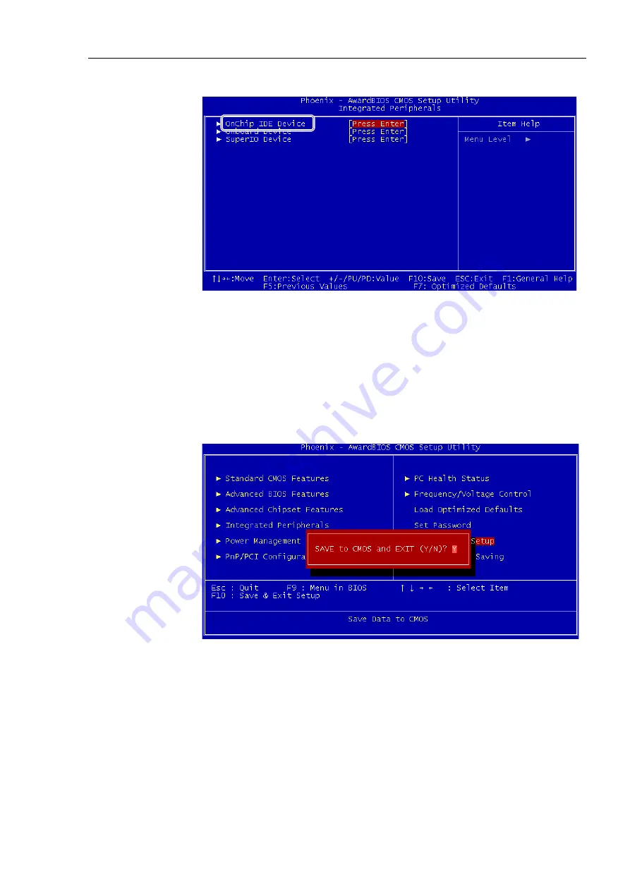
Select the [OnChip IDE Device]. 


Select the following in this order. 

[On Chip Serial ATA Settings] 

[On-Chip Serial ATA] 

[Enhanced Mode] 


Set the [Serial ATA Port 0 Mode] to “SATA0 Master”. 


Go back to the Main menu and select the [Save & Exit Setup]. 


Select “Y” and save the changed BIOS setting.   


(6)  Make sure the Controller operate properly without any trouble.   


Содержание RC620 CU

Страница 1: ...Rev 8 EM15XC3076F ROBOT CONTROLLER RC620 ...

Страница 2: ...ROBOT CONTROLLER RC620 Rev 8 ...

Страница 3: ...RC620 Rev 8 i ROBOT CONTROLLER RC620 Rev 8 Copyright 2009 2015 SEIKO EPSON CORPORATION All rights reserved ...

Страница 4: ... at all times RC620 robot controller consists of the following RC620 CU Control Unit RC620 DU Drive Unit This manual contains the information for the RC620 CU Control Unit For RC620 DU Drive Unit refer to the Robot Controller Drive Unit RC620DU manual The information for the robot controller is describes as below indicating both RC620 CU and RC620 DU Robot controller Controller RC620 The informati...

Страница 5: ... Damage or malfunction caused by improper use which is not described in the manual or careless use 2 Malfunctions caused by customers unauthorized disassembly 3 Damage due to improper adjustments or unauthorized repair attempts 4 Damage caused by natural disasters such as earthquake flood etc Warnings Cautions Usage 1 If the robot system associated equipment is used outside of the usage conditions...

Страница 6: ... refers generically to Windows XP Windows Vista and Windows 7 NOTICE No part of this manual may be copied or reproduced without authorization The contents of this manual are subject to change without notice Please notify us if you should find any errors in this manual or if you have any comments regarding its contents INQUIRIES Contact the following service center for robot repairs inspections or ...

Страница 7: ...Europe Epson Deutschland GmbH Factory Automation Division Otto Hahn Str 4 D 40670 Meerbusch Germany TEL 49 0 2159 538 1391 FAX 49 0 2159 538 3170 E MAIL robot infos epson de China Epson China Co Ltd Factory Automation Division 7F Jinbao Building No 89 Jinbao Street Dongcheng District Beijing China 100005 TEL 86 0 10 8522 1199 FAX 86 0 10 8522 1120 Taiwan Epson Taiwan Technology Trading Ltd Factory...

Страница 8: ... One Singapore 098633 TEL 65 0 6586 5696 FAX 65 0 6271 3182 India Epson India Pvt Ltd Sales Marketing Factory Automation 12th Floor The Millenia Tower A No 1 Murphy Road Ulsoor Bangalore India 560008 TEL 91 80 3051 5000 FAX 91 80 3051 5005 Japan Epson Sales Japan Corporation Factory Automation Systems Department Nishi Shinjuku Mitsui Bldg 6 24 1 Nishishinjuku Shinjuku ku Tokyo 160 8324 Japan TEL 8...

Страница 9: ...ort of RC620 Connecting to the followings may result in malfunction of the device since the pin assignments are different OPTIONAL DEVICE dummy plug Operation Pendant OP500 Operator Pendant OP500RC Operator Panel OP1 Jog Pad JP500 Teaching Pendant TP 3 Security support for the network connection The network connecting function Ethernet on our products assumes the use in the local network such as t...

Страница 10: ...Names and Functions 14 2 1 Part Names 14 2 2 Functions 16 2 3 LED and LCD 19 2 4 Safety Features 22 3 Installation 24 3 1 Unpacking 24 3 2 Environmental Requirements 24 3 2 1 Environment 24 3 2 2 Installation 25 3 3 Power Supply 26 3 3 1 Specifications 26 3 3 2 AC Power Cable 27 3 4 Cable Connection 27 3 4 1 Typical Cable Connection 28 3 4 2 Connecting Manipulator to Controller 29 3 5 Noise Counte...

Страница 11: ... Function 36 5 2 1 Precautions 36 5 2 2 Adoptable USB Memory 37 5 3 Controller Status Storage Function 37 5 3 1 Controller Status Storage with Trigger Button 37 5 3 2 Controller Status Storage with Teach Pendant Option 38 5 3 3 Load Data with EPSON RC 6 0 38 5 3 4 Transfer with E mail 39 5 4 Details of Data 40 6 LAN Ethernet Communication Port 41 6 1 About LAN Ethernet Communication Port 41 6 2 IP...

Страница 12: ...Assignment 56 10 I O Remote Settings 57 11 R I O Connector 58 11 1 Input Circuit 58 11 2 Pin Assignment 59 12 Option Units 60 12 1 What are Option Units 60 12 2 Expansion I O Board 61 12 2 1 About Expansion I O Board 61 12 2 2 Board Configuration Expansion I O 61 12 2 3 Confirmation with EPSON RC 6 0 62 12 2 4 Input Circuit 62 12 2 5 Output Circuit 64 12 2 6 Pin Assignments 66 12 3 Fieldbus I O Bo...

Страница 13: ...irect Teaching 92 14 3 TEACH Mode 94 14 3 1 Jog Teach 95 14 3 2 Point Editor 99 14 3 3 Robot 101 14 3 4 Motion Command 102 14 3 5 I O Command 103 14 3 6 Jog Distance 104 14 3 7 Free Joints 105 14 3 8 Brake For 6 Axis robots 106 14 4 AUTO Mode 108 14 4 1 Program Command Display 109 14 4 2 I O Monitor 110 14 4 3 Memory I O Monitor 110 14 4 4 Task Monitor 111 14 4 5 System History 112 14 4 6 Controll...

Страница 14: ... Tagout 124 2 Regular Maintenance Inspection 125 2 1 Schedule for Maintenance Inspection 125 2 2 Inspection Point 126 2 2 1 Inspection While the Controller is Turned OFF 126 2 2 2 Inspection While the Controller is Turned ON 126 3 Controller Structure 127 3 1 Location of Parts 127 3 2 Diagram of Cable Connections 127 3 3 Connector Pin Assignment 132 3 3 1 M C Power Connector 132 3 3 2 M C Signal C...

Страница 15: ... Board BIOS Backup Battery Memory 164 6 4 1 Normal 164 6 4 2 Faster 173 6 5 CF Compact Flash 186 6 6 Switching Power Supply 188 6 6 1 Switching Power Supply 15W 188 6 6 2 Switching Power Supply 75W 190 6 6 3 Switching Power Supply ATX 192 6 7 PCI Board 196 6 8 Special Board 198 6 8 1 Replacing the Special Option Board 198 6 8 2 Adding the Special Option Board 198 6 9 HDD 199 6 9 1 Standard HDD wit...

Страница 16: ...Table of Contents xiv RC620 Rev 8 8 Troubleshooting 208 If the display is blank 208 9 Maintenance Parts List 209 9 1 RC620 209 9 2 Option TP1 210 ...

Страница 17: ...Safety This section contains information for safety of the Robot System ...

Страница 18: ......

Страница 19: ...derations are indicated throughout the manual by the following symbols Be sure to read the descriptions shown with each symbol WARNING This symbol indicates that a danger of possible serious injury or death exists if the associated instructions are not followed properly WARNING This symbol indicates that a danger of possible harm to people caused by electric shock exists if the associated instruct...

Страница 20: ...ctive manuals This product has been designed and manufactured strictly for use in a normal indoor environment Using the product in an environment that exceeds the specified environmental conditions may not only shorten the life cycle of the product but may also cause serious safety problems The robot system must be used within the installation requirements described in the manuals Using the robot ...

Страница 21: ...ne by qualified personnel When connecting the plug be sure to connect the earth wire of the AC power cable colored green yellow on the Controller to the earth terminal of the factory power supply The equipment must be grounded properly at all times to avoid the risk of electric shock Always use a power plug and receptacle Never connect the Controller directly to the factory power supply Field wiri...

Страница 22: ...switch is disabled Example Tape is put around the switch to hold it closed Operating the robot system when the switch is not functioning properly is extremely hazardous and may cause serious safety problems as the Safety Door input cannot fulfill its intended function WARNING Do not open the cover s of the Controller except while maintaining it Opening the cover s of the Controller is extremely ha...

Страница 23: ...Setup Operation This section contains information for setup and operation of the Robot Controller ...

Страница 24: ...8 RC620 Rev 8 ...

Страница 25: ...BUS DP Remote I O DeviceNET EtherNet CC LINK RS 232C EtherNet IP PROFINET RS 232C Board Pulse Generating Board PCl slot Windows XP Frame Grabber Board Fieldbus I O Master Board EPSON RC 6 0 PROFIBUS DP DeviceNET Vision Guide 6 0 option EtherNet IP VB Guide 6 0 option GUI Builder 6 0 option Additional axis option Two units can be connected G RS C3 X5 Drive Unit Display Keyboard Mouse ...

Страница 26: ...ion control PTP motion Programmable in the range of 1 to 100 Automatic CP motion Programmable Actual value to be manually entered Connectable Manipulator Max 16 units Max 20 axes Positioning control PTP Point To Point control CP Continuous Path control Memory capacity Maximum Object Size 8 MB Point data area 1000 points per file Backup variable area Max 400 kB Includes the memory area for the mana...

Страница 27: ...eatures Emergency stop switch Safety door input Low power mode Dynamic brake Encoder cable disconnection error detection Motor overload detection Irregular motor torque out of control Manipulator detection Motor speed error detection Positioning overflow servo error detection Speed overflow servo error detection CPU irregularity detection Memory check sum error detection Overheat detection at the ...

Страница 28: ...spec 24 5 kg 8 axes spec 25 5 kg 1 Weight of the unit is indicated on the Controller itself Make sure to check the weight before units transfer or relocation and prevent throwing out your back at holding the unit Also make sure to keep your hands fingers and feet safe from being caught or serious injury ...

Страница 29: ...Setup Operation 1 Specifications RC620 Rev 8 13 1 3 Outer Dimensions Dimension of RC620 UL is the same as RC620 Unit mm 4 M4 NOTE ...

Страница 30: ... Part Names and Functions 14 RC620 Rev 8 2 Part Names and Functions 2 1 Part Names Front RC620 9 12 1 11 15 8 2 3 4 5 6 7 10 13 14 1 14 2 RC620 UL Side and Back are the same as RC620 9 12 1 15 8 2 3 4 5 6 7 13 14 1 14 2 ...

Страница 31: ...Setup Operation 2 Part Names and Functions RC620 Rev 8 15 Side 16 17 Back 28 18 19 20 21 23 24 25 26 27 29 30 31 32 33 34 22 ...

Страница 32: ...ort 4 Memory port This port connects the common USB memory for Controller status storage function Do not connect other USB devices except the USB memory For details refer to Setup Operation 5 Memory Port 5 HDD access LED This LED displays the HDD access condition 6 Shutdown switch If you want to shutdown the Windows when the keyboard is not connected use this switch turn it on Also if for some rea...

Страница 33: ... Number Label The label indicates the DU number and serial number of Drive Unit When connecting Drive Unit this label is attached according to the number of Drive Unit s 16 Signature label The serial number of the Controller and other information are shown 17 MT label The label indicates the specification number for the customized Manipulator and is attached only to the customized Manipulator If y...

Страница 34: ... the label as shown in the right The label indicates the Manipulator model and Manipulator serial number MANIPULATOR 00003 G3 351S 29 Connection Check label 1 The details of the Manipulator to be connected are recorded on the label as shown in the right The label indicates the Manipulator model and Manipulator serial number MANIPULATOR 00002 G3 351S 30 M C SIGNAL connector 2 option This connector ...

Страница 35: ...up and the 2nd line is turned off for approx 10 seconds Then for few seconds it displays as below EPSON Robot Controller After Controller Startup LED LED TEACH AUTO PROGRAM turns ON according to the current operation mode TEACH Auto Program LCD The display varies depending on the controller status The basic layout is shown below 1st Line 2nd Line Status EStop Safety Message Status Displays the con...

Страница 36: ...up Waiting for RC Error Err2200 r01a03 Robot in use Cannot 1 TEACH Teach V 6 0 0 1 READY Ready V 6 0 0 1 2 PAUSE Task123 P1234 Paused 2 START Task123 L1234 Tasks Running 2 1 For error numbers and warning numbers refer to SPEL Language Reference manual The 1st line displays Err and 4 figures For the error numbers refer to the SPEL Language Reference manual XX in rXXaYY is a robot number and YY is a...

Страница 37: ...er message when Print 28 specifies the message Particular Status Display When particular status occurs LCD displays the followings LCD Status Initialize Error 16 Controller startup failure 1 P Controller startup mode Controller startup failure 9999 Recovery Mode Controller in Recovery mode Refer to Maintenance 4 Backup and Restore 9998 AC Power Off AC power supply drop is detected and software shu...

Страница 38: ...pulator operation while the safety door is open you must change the mode selector key switch on the Teach Pendant to the Teach mode Manipulator operation is available only when the enable switch is on In this case the Manipulator is operated in low power mode Low Power Mode The motor power is reduced in this mode Executing a power status change instruction will change to the restricted low power s...

Страница 39: ...he Controller are also designed to constantly check each other for any discrepancies If a discrepancy is detected the dynamic brake circuit is activated Memory Check sum Error Detection The dynamic brake circuit is activated when a memory check sum error is detected Overheat Detection at the Motor Driver Module The dynamic brake circuit is activated when the temperature of the power device inside ...

Страница 40: ...nvironment that exceeds the conditions may not only shorten the life cycle of the product but also cause serious safety problems 3 2 1 Environment In order to optimize the robot system s performance for safety the Controller must be placed in an environment that satisfies the following conditions The Controller is not designed for clean room specification If it must be installed in a clean room be...

Страница 41: ...y and horizontally When you place it vertically place the left side from front side view down Also put the rubber feet on the bottom to the left side Use the same screws for securing the rubber feet Position of set screws for rubber feet Make sure to keep the controller away from the peripherals for the air supply and exhaust Controller Front side 100 mm Rear side 150 mm The rear side exhausts the...

Страница 42: ...or rated consumption Rated power consumption of X5 varies depending on the manipulator model For details please contact us Peak Current When power is turned ON approx 80 A 2 msec When motor is ON approx 50 A 5 msec Leakage Current Max 10 mA Ground Resistance 100 Ω or less Install an earth leakage circuit breaker or a circuit breaker in the AC power cable line at 15 A or less rated electric current...

Страница 43: ...e National Electrical Code A disconnecting means shall be installed in accordance with the National Electrical Code and provide the ability for lockout and tagout 3 4 Cable Connection WARNING Make sure that the power to the Controller is turned OFF and the power plug is disconnected before connecting or disconnecting any cables Connecting or disconnecting any cables with the power ON is extremely ...

Страница 44: ... cable 6 LAN Cable 1 AC Power cable Cable for AC 200V power input to the Controller 2 M C Power cable Connect the motor power signals between the Manipulator and Controller Insert the connectors on the Controller until you hear a click 3 M C Signal cable Connect the encoder signals between the Manipulator and the Controller Secure this cable to the Controller for sure using the set screws on both ...

Страница 45: ...sconnecting any cables with the power ON is extremely hazardous and may result in electric shock and malfunction of the Controller Be sure to connect the cables properly Do not allow unnecessary strain on the cables Do not put heavy objects on the cables Do not bend or pull the cables forcibly The unnecessary strain on the cables may result in damage to the cables disconnection and or contact fail...

Страница 46: ...the Controller power line by at least 200 mm from the sensor or valve I O lines and do not bundle both sets of wiring with the same cable tie If more than one duct cable must cross each other they should cross perpendicularly The preferable example is shown in the right figure AC Line duct DC line duct 200 mm or more Wire as short as possible to the I O connector and EMERGENCY connector Use a shie...

Страница 47: ...ution of the Robot system for the manufacturing operation and also programming debug adjustment and maintenance of the Robot system This mode cannot operate the Robots or run programs with the Safety Door open 4 2 Switch Operation Mode Change the operation mode using the mode selector key switch on the Teach Pendant TEACH mode Turn the mode selector key switch to Teach for TEACH mode Switching to ...

Страница 48: ...ching to the Program mode are the followings Set the start mode of the EPSON RC 6 0 to Program and start up the Controller 4 3 2 Setup from EPSON RC 6 0 Switch the start mode to Program mode from the EPSON RC 6 0 1 Select EPSON RC 6 0 menu Setup System Configuration to display the System Configuration dialog 2 5 3 4 2 Select Startup 3 Select Start mode Program button 4 Click the Apply button 5 Cli...

Страница 49: ...6 0 to Auto and start the Controller B Set the Controller to the Independent mode Execute and stop the program from the control device specified by the EPSON RC 6 0 Refer to 4 4 3 Setup Control Device 4 4 2 Setup EPSON RC 6 0 Switch the Start mode to Auto mode AUTO 1 Select EPSON RC 6 0 menu Setup System Configuration to display the System Configuration dialog 2 5 3 4 2 Select Startup 3 Select Sta...

Страница 50: ...System Configuration to display the System Configuration dialog 2 Select SPEL Controller Board Preference 2 5 3 4 3 Check Independent Mode check box 4 Click the Apply button 5 Click the Close button For the details of Independent mode refer to the EPSON RC 6 0 Users Guide 4 2 1 Startup Sequence Cooperative mode and Independent mode ...

Страница 51: ...ON RC 6 0 1 Select EPSON RC 6 0 menu Setup System Configuration to display the System Configuration dialog 2 5 3 4 1 Select SPEL Controller Board Configuration 2 Select Setup Controller Control Device to select the control device from the following two types Self Remote I O 3 Click the Apply button 4 Click the Close button ...

Страница 52: ...ntroller and the program simply and accurately The saved data can also be used for restoring the Controller For details refer to Maintenance 4 4 Restore 5 2 Before Using Controller Status Storage Function 5 2 1 Precautions CAUTION Controller status storage function is available at any time and in any Controller status after starting the Controller However operations form the console including stop...

Страница 53: ...tatus of the Controller to USB memory 1 Insert the USB memory into the memory port 2 Wait approximately 10 seconds for USB memory recognition 3 Press the trigger button on the Controller The LCD displays the following repeatedly during the data transfer Status Backup Status Backup Wait for the display to turn back to the normal Data transfer time depends on the project size etc 4 When the storage ...

Страница 54: ...y default 4 Press the OK key to save the status 5 3 3 Load Data with EPSON RC 6 0 The following shows the procedure to read the data stored in the USB memory by EPSON RC 6 0 and display the Controller status 1 Insert the USB memory into the PC with EPSON RC 6 0 2 Make use that the following folder is indicated in the USB memory S_ serial number_data status was saved Exmaple S_12345_200608074410 3 ...

Страница 55: ...ools Menu 5 3 4 Transfer with E mail Follow this procedure to transfer the data by e mail that was saved to the USB memory 1 Insert the USB memory to a PC that supports sending of e mail 2 Make sure that the USB memory has following folders S_serial number_data status was saved Example S_12345_200608074410 3 Send all the folders by e mail Delete files that do not relate to the project before trans...

Страница 56: ...nected robot for each robot SrcmcStat txt Hardware information Saves installation information of hardware ProjectName obj OBJ file Result of project build Prg file is not included GlobalPreserves dat Global Preserve variables Saves values of Global Preserve variables MCSRAM bin MCSYSTEMIO bin MCTABLE bin MDATA bin VXDWORK bin Inner information of Robot operation All files related to project except...

Страница 57: ...20 Controller has two ports LAN 1 and LAN 2 Both are Ethernet communication ports and support 100BASE TX 10 BASE T These two ports are used for the following purposes LAN 1 port SPEL dedicated Ethernet port Connection with other Controller or PC This port can be used as an Ethernet TCP IP communication port to communicate between multiple controllers from robot application software Connection with...

Страница 58: ...LAN 1 port cannot automatically acquire the IP address not support DHCP LAN 2 port This port can acquire the IP address automatically 6 3 Changing IP Address 6 3 1 LAN 1 port Change the IP address of LAN 1 port 1 Select the EPSON RC 6 0 menu Setup Controller to display the Setup Controller dialog 2 Enter the proper IP address and subnet mask and click the Apply button 3 Click the Close button The ...

Страница 59: ...Setup Operation 6 LAN Ethernet Communication Port RC620 Rev 8 43 6 3 2 LAN 2 port The IP address of LAN 2 port can be changed in the normal steps of Windows ...

Страница 60: ...ort of RC620 Connecting these devices may result in malfunction of the device since the pin assignments are different OPTIONAL DEVICE dummy plug Operation Pendant OP500 Jog Pad JP500 Operator Pendant OP500RC Teaching Pendant TP 3 Be careful of the operating instructions of the TP1 when connecting it to the Robot Controller RC180 RC170 it is different from the explanation in this manual Setup opera...

Страница 61: ...e Connect a safeguard switch or Emergency Stop switch to the Controller EMERGENCY connector for safety When nothing is connected to the EMERGENCY connector the Controller does not operate normally WARNING Before connecting the connector make sure that the pins are not bent Connecting with the pins bent may damage the connector and result in malfunction of the robot system EMERGENCY connector NOTE ...

Страница 62: ...lator The safeguard must have an interlock switch at the entrance to the working zone The Safety Door that is described in this manual is one of the safeguards and an interlock of the Safety Door is called a Safety Door switch Connect the Safety Door switch to the Safety Door input terminal on the EMERGENCY connector The Safety Door switch has safety features such as temporary hold up of the progr...

Страница 63: ...ration for safety by following the procedures described below before operating the Manipulator 1 Turn ON the Controller while the safety door is open in order to boot the controller software 2 Make sure that the Controller LCD displays the one of the following SG Safety 3 Make sure that Safety is displayed on the main window status bar 4 Close the safety door and turn ON the switch connecting to t...

Страница 64: ...ecified pins on the EMERGENCY connector at the Controller Refer to the Setup Operation 8 4 Circuit Diagrams 8 2 2 Checking Emergency Stop Switch Operation Once the Emergency Stop switch is connected to the EMERGENCY connector continue the following procedure to make sure that the switch functions properly For the safety of the operator the Manipulator must not be powered ON until the following tes...

Страница 65: ...GND output 25 24VGND 24V GND output 13 NC 1 Do not connect anything to these pins 2 A critical error occurs if the input values from the Safety Door 1 and Safety Door 2 are different for two or more seconds They must be connected to the same switch with two sets of contacts 3 A critical error occurs if the input values from the Emergency Stop switch contact 1 and Emergency Stop switch contact 2 ar...

Страница 66: ...1 External 24V Safety Door input 2 Latch release input Latch release input Close Latch off Open Latch on Main Circuit Control AC Input Emergency Stop switch of an Operation Unit TP External 24V GND External Emergency Stop switches Motor Driver Controller 9 10 22 23 1 2 14 15 3 16 4 17 11 12 24 25 7 8 20 21 18 19 Emergency Stop detection NOTE 24V GND 5V GND ...

Страница 67: ...elay The above diagram is simplified for representation External 24V GND 24V 5V Safety Door input 1 Safety Door input 2 Latch Release input AC Input Motor Driver External 24V Fuse External 24V Controller 9 10 22 23 1 2 14 15 3 16 4 17 11 12 24 25 7 8 20 21 18 19 Main Circuit Control Emergency Stop switch of an Operation Unit TP Emergency Stop detection External 24V Latch release input Close Latch ...

Страница 68: ...24 256 to 279 Output 16 256 to 271 For details of the expanded I O to be installed to the Special slot refer to Setup Operation 11 2 Expansion I O Board For cable wiring refer to the Setup Operation 3 5 Noise Countermeasures in order to prevent noise 9 1 Input Circuit Input Voltage Range 12 to 24 V 10 ON Voltage 10 8 V min OFF Voltage 5 V max Input Current 10 mA TYP at 24 V input Two types of wiri...

Страница 69: ... Input No 7 I O 1 Same Omit GND DC 18 Input No 8 to 15 common 19 Input No 8 20 Input No 9 Same Same Same Same Same Same Same Typical Input Circuit Application 2 1 Input No 0 to 7 common 2 Input No 0 3 Input No 1 4 Input No 2 5 Input No 3 6 Input No 4 7 Input No 5 8 Input No 6 9 Input No 7 I O 1 Same Omit GND DC 18 Input No 8 to 15 common 19 Input No 8 20 Input No 9 Same Same Same Same Same Same Sa...

Страница 70: ...t Circuit Rated Output Voltage 12 V to 24 V 10 Maximum Output Current TYP 100 mA 1 output Output Driver PhotoMOS Relay On State Resistance average 23 5 Ω or less Two types of wiring are available for use with the nonpolar photoMOS relay in the output circuit ...

Страница 71: ...tput No 7 17 Output No 0 to 7 common GND Load L GND L 33 Output No 8 to 15 common GND Same Same Same Same Same Same Same Same Typical Output Circuit Application 2 10 Output No 0 I O 1 Same Omit DC 29 Output No 8 30 Output No 9 11 Output No 1 12 Output No 2 13 Output No 3 14 Output No 4 15 Output No 5 27 Output No 6 28 Output No 7 17 Output No 0 to 7 common DC Load L GND L 33 Output No 8 to 15 comm...

Страница 72: ...24 Input No 13 40 Input No 21 8 Input No 6 25 Input No 14 41 Input No 22 9 Input No 7 26 Input No 15 42 Input No 23 10 Output No 0 27 Output No 6 43 Output No 11 11 Output No 1 28 Output No 7 44 Output No 12 12 Output No 2 29 Output No 8 45 Output No 13 13 Output No 3 30 Output No 9 46 Output No 14 14 Output No 4 31 Output No 10 47 Output No 15 15 Output No 5 32 NC 48 NC 16 NC 33 Output common No ...

Страница 73: ...I O manual CAUTION When using remote I O always make sure of the following Using the robot system under unsatisfactory conditions may cause malfunction of the system and or safety problems Assign remote functions to inputs outputs correctly and wire correctly when setting up remote I O signals Make sure that the functions correspond to the correct input output signals before turning ON the system ...

Страница 74: ... O you can keep and get the operating robot position when trigger is detected If you use this function with Vision you can create an application of parts pickup alignment and assembly by robots without stopping For details refer to EPSON RC 6 0 Users Guide Real time I O In the case of 6 axis robot this function can not be used 11 1 Input Circuit Input Voltage Range 24 V 10 Input Current 10 mA TYP ...

Страница 75: ...Connector Standard I O Connector Controller side D sub 50 male pin Mounting style 4 40 CAUTION When using R I O connector be careful of the following points If you use the R I O connector without meeting the necessary conditions it may cause the system failure and or safety problems Use a shielded cable and route the cables as far from the surrounding noise sources as possible For details refer to...

Страница 76: ... RC620 OptionPG Motion system manual Max 3 PCI boards can be installed to the PCI slots As the option board the following 2 types are provided Frame grabber board Refer to the EPSON RC 6 0 Option Vision Guide 6 0 manual Fieldbus I O master board Refer to the RC620 Option Fieldbus I O manual Of the PCI slots a slot next to the CPU board has to limit the height of parts on the board to avoid the int...

Страница 77: ... to 127 The 2nd Expansion I O board 128 to 159 128 to 159 The 3rd Expansion I O board 160 to 191 160 to 191 The 4th Expansion I O board 12 2 2 Board Configuration Expansion I O Board Appearance Switch and Jumper Configuration CN1 CN2 DSW2 DSW1 CN4 Setup the DSW1 and DSW2 CN4 is all open 1st board 2nd board 3rd board 4th board SW4 SW3 SW2 SW1 DSW2 ON 1 2 3 4 SW8 SW7 SW6 SW5 SW4 SW3 SW2 SW1 1 2 3 4 ...

Страница 78: ... 6 0 1 Select the EPSON RC 6 0 menu Setup System Configuration to display the System Configuration dialog 2 Select the Inputs Outputs 3 Make sure that Yes is displayed in the Installed column The expansion I O board is identified by the Controller software Corresponding Input and Output is available 12 2 4 Input Circuit Input Voltage Range 12 V to 24 V 10 ON Voltage 10 8 V Min OFF Voltage 5 V Max ...

Страница 79: ...on I O board 1 Same Omit GND DC 18 Input No 72 to 79 common 19 Input No 72 20 Input No 73 Same Same Same Same Same Same Same Protected Expansion I O Board Typical Input Circuit Application 2 1 Input No 64 to 71 common 2 Input No 64 3 Input No 65 4 Input No 66 5 Input No 67 6 Input No 68 7 Input No 69 8 Input No 70 9 Input No 71 Expansion I O board 1 Same Omit GND DC 18 Input No 72 to 79 common 19 ...

Страница 80: ...available for use with the nonpolar photoMOS relay in the output circuit Protected Expansion I O Board Typical Output Circuit Application 1 10 Output No 64 11 Output No 65 12 Output No 66 13 Output No 67 14 Output No 68 15 Output No 69 27 Output No 70 28 Output No 71 17 Output No 64 to 71 common GND Expansion I O 1 Same Omit DC 29 Output No 72 30 Output No 73 33 Output No 72 to 79 common GND Load ...

Страница 81: ...ation 2 10 Output No 64 11 Output No 65 12 Output No 66 13 Output No 67 14 Output No 68 15 Output No 69 27 Output No 70 28 Output No 71 17 Output No 64 to 71 common Expansion I O 1 Same Omit DC 29 Output No 72 30 Output No 73 33 Output No 72 to 79 common Load GND L L Same Same Same Same Same Same Same Same ...

Страница 82: ...39 NC 7 Input No 69 24 Input No 77 40 NC 8 Input No 70 25 Input No 78 41 NC 9 Input No 71 26 Input No 79 42 NC 10 Output No 64 27 Output No 70 43 Output No 75 11 Output No 65 28 Output No 71 44 Output No 76 12 Output No 66 29 Output No 72 45 Output No 77 13 Output No 67 30 Output No 73 46 Output No 78 14 Output No 68 31 Output No 74 47 Output No 79 15 Output No 69 32 NC 48 NC 16 NC 33 Output commo...

Страница 83: ... No 86 43 Output No 91 11 Output No 81 28 Output No 87 44 Output No 92 12 Output No 82 29 Output No 88 45 Output No 93 13 Output No 83 30 Output No 89 46 Output No 94 14 Output No 84 31 Output No 90 47 Output No 95 15 Output No 85 32 NC 48 NC 16 NC 33 Output common No 88 to 95 49 NC 17 Output common No 80 to 87 50 NC Connector Standard I O Connector Controller side D sub 50 male pin Mounting style...

Страница 84: ...board 5 to 8 Second RS 232C board 12 4 2 Board Setup RS 232C Board Appearance Switch and Jumper Configuration CN1 CN2 CN3 CN4 JMP1 DSW2 DSW1 CN6 Set DSW1 DSW2 and JMP1 CN6 is all open 1st board 2nd board SW4 SW3 SW2 SW1 DSW2 ON 1 2 3 4 SW8 SW7 SW6 SW5 SW4 SW3 SW2 SW1 1 2 3 4 5 6 7 8 ON DSW1 IRQ15 IRQ11 IRQ10 IRQ7 IRQ5 JMP1 JP5 JP4 JP3 JP2 JP1 1 2 CN6 1 2 9 10 SW4 SW3 SW2 SW1 DSW2 ON 1 2 3 4 SW8 SW...

Страница 85: ... 6 0 1 Select the EPSON RC 6 0 menu Setup System Configuration to display the System Configuration dialog 2 Select the RS 232C RC620 controller has one or two communication ports as standard When using the communication ports you should enable the port 1001 and 1002 by checking the Enabled check box If no RS 232C board is installed controller of the RS 232C will not be displayed RS 232C is automat...

Страница 86: ...ontroller side D sub 9 male pin Mounting style 4 40 Use twisted pair cable for shielded wire Clamp the shield to the hood for noise prevention Pin assign of the RS 232C connector is as follows Pin No Signal Function Signal Direction 1 DCD Data carrier detect Input 2 RXD Receive data Input 3 TXD Send data Output 4 DTR Terminal ready Output 5 GND Signal ground 6 DSR Data set ready Input 7 RTS Reques...

Страница 87: ...anipulator is operating an error such as an encoder communication error occurs and the Manipulator makes an emergency stop Normal Shutdown of Robot System Exit EPSON RC 6 0 and shut down Windows After the Windows shutdown make sure the LCD panel is turned OFF and then turn OFF the power switch of the Controller Automatic Shutdown by UPS service in Robot System For RC620 the UPS service of the Wind...

Страница 88: ... dispose of a used battery properly please inquire of your EPSON robot supplier how to dispose of it Charging Battery Turning ON the Controller will automatically charge the UPS battery To completely charge a discharged UPS battery turn ON the Controller and keep it energized for at least 2 hours after the backup operation Life Cycle of Battery The battery is expendable To maintain the Controller ...

Страница 89: ...aching or calibration of the robot system The safety training is the program for industrial robot operator that follows the laws and regulations of each nation The personnel who have taken the safety training acquire knowledge of industrial robots operations teaching etc The personnel who have completed the robot system training class held by the manufacturer dealer or locally incorporated company...

Страница 90: ... cause serious safety problems WARNING When entering the safeguarded area for teaching change the mode of the Teach Pendant to TEACH and take out the key for the mode selector key switch and then enter the safeguarded area with the key Leaving the key in the mode selector key switch is extremely hazardous and may cause serious safety problems as someone else may inadvertently change the mode to th...

Страница 91: ...witch on the Teach Pendant functions properly Operating the Teach Pendant when the switch does not function properly is extremely hazardous and may result in serious bodily injury and or serious damage to the equipment as the switch cannot fulfill its intended function in an emergency When nothing appears on its display window the Teach Pendant is not connected with the Controller In this case the...

Страница 92: ... Using Teach Pendant in Safeguarded Area When the mode selector switch of the Teach Pendant is switched to Teach mode the operator can jog and move the robot to predefined points in slow speed when the enable switch is gripped and the safeguard is open Personnel that will be using the Teach Pendant should be thoroughly trained on how to use it Follow these guidelines when using the Teach Pendant i...

Страница 93: ...rgency Stop state is held both mechanically and electrically Pushing the switch stops the program removes power to robot motors and stops the manipulator motion immediately To cancel the Emergency Stop state first turn the EMERGENCY STOP switch to the right to release the mechanical latch Switch the mode selector key switch to Teach Press the Reset key to reset the electrically held Emergency Stop...

Страница 94: ...h Pendant Standard Specifications Item Specification General specifications Rated voltage DC24 V Electric power consumption 6 W or less Weight 1075 g include EMERGANCY STOP switch and the mode selector key switch excluding cables Display specifications Display element F STN type Black and white LCD Contrast 8 level Gray scale Back light LED Color White Serial interface specifications Electrical ch...

Страница 95: ...rop the Teach Pendant or hit hard against other objects to avoid damage as the case of the Teach Pendant may be damaged since the main body is made of resin Use the hand strap to prevent dropping the Teach Pendant during operation Do not hit the touch panel of the Teach Pendant against a hard object or put excessive pressure on it The touch panel is made of glass Therefore if excessive pressure is...

Страница 96: ... Pendant TP1 to the TP port be careful of the connector inserting direction up down It may cause malfunction and result in improper function of the system Typical cable connection The Teach Pendant is connected to TP port of controller RC620 When nothing is connected to the TP port Emergency Stop status occurs to the Controller When the Teach Pendant is not connected connect the TP OP bypass plug ...

Страница 97: ... is ON When Teach Pendant connector is removed from the Controller RC620 with the mode selector key switch of Teach Pendant that is in Teach position the operation mode will remain in TEACH mode The operation mode cannot be switched to AUTO mode Make sure to remove the Teach Pendant after switching the operation mode to Auto mode Power Supply The power of the Teach Pendant is supplied via the TP p...

Страница 98: ...ration 14 Option Teach Pendant TP1 82 RC620 Rev 8 Wall Bracket Option Outer Dimension Hook A Hook B 201 4 31 4 100 118 56 2 100 226 6 6 6 6 39 6 392 9 Detail J K J Detail K Front View Back View Side View Unit mm ...

Страница 99: ...endant with the wall bracket in the following procedures 1 Secure the wall bracket to the wall with three screws positions are indicated by dotted line in the Outer Dimension 2 Hang the handle of the Teach Pendant to Hook A 3 Hang the cable of the Teach Pendant to Hook B Teach Pendant Cable ...

Страница 100: ...atus AUTO mode This mode enables automatic operation program execution of the Robot system at the manufacture operation besides programming debug adjustment and maintenance of the Robot system This mode cannot operate Robots or run program with the Safety Door open TEACH mode Jog Teach 13 3 1 Jog Teach F1 Point Editor 13 3 2 Point Editor F2 Robot 13 3 3 Robot F3 Motion Command 13 3 4 Motion Comman...

Страница 101: ...a Time Brightness Contrast 13 4 8 Brightness Contrast Language 13 4 9 Language Error 13 4 10 Error NAME Screen name Reference section Switch Operation Mode Change the TEACH mode and AUTO mode with the mode selector key switch on the Teach Pendant TEACH mode Turn the mode selector key switch to Teach for TEACH mode Pauses the executing program when operation mode is switched to TEACH mode The opera...

Страница 102: ...eys Teaching keys Safety lamp Alphabet and Number Input Keys Input mode alphabet number switches by turning ON OFF the Alph lamp Press the Alph Num key to turn ON OFF the Alph lamp Alph Mode Key Function OFF Number input mode From 0 to 9 minus period Number input ON Alphabet input mode ABC to WXYZ Alphabet input SP space Space input a A Case selector Sym Symbol input Common CLR Clear number and al...

Страница 103: ...rsor to the left Jog key switch J4 J5 J6 J7 J8 J9 Move the cursor to the right Jog key switch J4 J5 J6 J7 J8 J9 ON Scroll mode 10 the value Move to previous page 10 the value Move to next page Function Keys Press the F5 8 key to turn ON OFF the F5 8 lamp The display will be changed Example Jog Teach Screen F5 8 OFF F1 F2 F3 F4 F5 8 ON F5 F6 F7 F8 Example Press the F3 key to display the Motion scre...

Страница 104: ... Jog Dist Specifies the Jog distance Speed Specifies the Jog speed Teach Saves the current position data Other keys Key Function Cancel Cancels the setting and go back to the previous screen Click the No button OK Saves the setting and move on to the next screen Click the Yes button Reset Sets the initial setup status Motor Switches the motor power ON OFF Home Moves the robot to home position Keys...

Страница 105: ...ch with the left hand fingers until it just stops at the center detent If you pull harder or let go then the switch will be disengaged and the operation will be canceled Enable Switch for Left Hand Back view Left side view Right side view Enable Switch for Right Hand For RC620 UL When the enable switch is off the manipulator is in Motor Off status How to press the Enable switch Grip the enable swi...

Страница 106: ...e following operation Step Jog operation Continuous Jog operation Step Jog Operation In Step Jog moves the Robot by pressing the Jog key each time Jog distance of the Robot is configured beforehand Press the Jog Dist key to specify the Jog Dist Long Medium Short Execute the step jog by gripping the enable switch as pressing the Jog key Continuous Jog Operation In Continuous Jog moves the Robot whi...

Страница 107: ...each screen Label display changes by changing the point number 2 Press the Teach key The following screen appears When the point number is already used the following screen appears 3 Press the OK key to assign the robot position 4 Press the Save Points key to display the following screen 5 Press the OK key to save the file Press the Cancel key to returns to the Jog Teach screen without saving the ...

Страница 108: ...oint using the and keys in the Jog Teach screen Label display changes by changing the point number 2 Press the F5 8 key F6 key the following screen appears Set each joint to servo ON or OFF Jog key Lock Servo OFF the joint Jog key Free Servo ON the joint F2 key All Lock Servo OFF all the joint F3 key All Free Servo ON all the joint For the Jog keys operation refer to Operation 14 3 1 Jog Teach Jog...

Страница 109: ... When the point number is already used the following screen appears 7 Press the OK key to assign the robot position 8 Press the Save Points key to display the following screen 9 Press the OK key to save the file Press the Cancel key to returns to the Jog Teach screen without saving the changes of the file NOTE ...

Страница 110: ...r that the program cluster cannot be executed TEACH mode Jog Teach 13 3 1 Jog Teach F1 Point Editor 13 3 2 Point Editor F2 Robot 13 3 3 Robot F3 Motion Command 13 3 4 Motion Command F4 I O Command 13 3 5 I O Command F5 Jog Distance 13 3 6 Jog Distance F6 Free Joints 13 3 7 Free Joints F8 Brake 13 3 8 Brake For 6 Axis robots F1 F8 Function key NAME Screen name Reference section A coordinate point i...

Страница 111: ...fy a point number Changing the point number changes the indication at Label Specifying Jog Mode Press the Jog Mode key and specify the Jog Mode World Tool Joint ECP The default setting is World World Jogs the robot along the X Y Z axes in the current local tool arm and ECP For robots with 4 DOF you can also jog U roll For robots with 6 DOF you can jog U roll V pitch and W yaw This is the default s...

Страница 112: ...rection or joint is displayed in the left side of the Jog key If the robot has 6 or more axes the three keys shown below are switched when pressing the keys Example U V W R S T J4 J5 J6 J7 J8 J9 When the additional S axis is set on the 6 axis robot the key display is changed as shown below to move the additional S axis When the Jog keys are not displayed the robot cannot move by pressing keys NOTE...

Страница 113: ...continuous jog the robot moves continuously while the Jog key is held down 1 Press the Jog Dist key and select Cont Jog at Jog Dist When the F5 8 key lights up its LED the toggle of Jog Dist key is the opposite direction 2 To execute continuous jog grip the enable switch while pressing the Jog key ON OFF Refer to 14 3 7 Free Joints Motor ON OFF Press the Motor key to switch the motor ON and OFF Th...

Страница 114: ...ress the Save Points key This can also be executed in the Point Editor screen Saving Point File 1 Press the Save Points key The following screen appears 2 Press the OK key to save the positions to the file This can also be executed in the Point Editor screen Loading Point File 1 Press the LoadPoints key The following screen appears Move the cursor to select a file TIP TIP ...

Страница 115: ...een This can also be executed in the Point Editor screen 14 3 2 Point Editor This section indicates settings in the Point Editor screen 1 Press the F1 key in the Jog Teach screen The following screen appears 2 Set the data items currently displayed in the Point Editor screen See described hereinafter Specifying Point Number Changing Point Label Changing Coordinate Data and Pose Flag Deleting Point...

Страница 116: ...er to change the indication at Label Changing Point Label 1 Press the F1 key and move the cursor to Label 2 Enter the label name at Label to set the name 3 Press the Enter key 4 Press the OK key to apply the memory Changing Coordinate Data and Pose Flag 1 Press the F2 key and move the cursor to Position X 2 Move the cursor and set the coordinate data pose flag To change the orientation flag point ...

Страница 117: ...and move the cursor to Robot 2 Change the robot number 3 Press the Enter key 4 Label display changes by changing the robot number 5 Press the OK key to save the settings The display of the Robot is changed in the step 3 Save the robot setting before changing the numbers of Arm Tool Local and ECP Changing the numbers of Arm Tool Local ECP Set the robot number first and then change the numbers of Ar...

Страница 118: ...ss the OK key to execute the motion command To execute motion command grip the enable switch while pressing the OK key Robots except 6 Axis robots This item indicates the procedure for executing motion commands when using the robots except the 6 axis robots 1 Press the F3 key in the Jog Teach screen The following screen appears Move the cursor to the desired motion command and press the OK key 2 T...

Страница 119: ... Jog Teach screen The following screen appears Switching Input Output Status Display Press the F3 key to switch between the Inputs status and the Outputs status display Output Bit ON OFF 1 Press the F3 key to display the Outputs status 2 Move the cursor to the output bit that you want to change 3 Switch the ON OFF status of the output bit F1 key On F2 key Off ...

Страница 120: ... to save the settings Changing Jog Distance Set the jog distance The current jog mode and jog distance are displayed You can change these settings by pressing the Jog Mode or Jog Dist key When the F5 8 key lights up its LED the toggles of Jog Mode and Jog Dist keys are the opposite direction 1 Press the keys and move the cursor to change an item 2 Change the Jog Distance 3 Press the Enter key 4 Pr...

Страница 121: ... Off for each joint When performing direct teaching manually moving the robot by hand to perform teaching set the joint to Off Press the Jog Dist key and select Free Joint at Jog Dist Set On Off for each joint key Lock Sets the joint to Off key Free Sets the joint to On F2 key All Lock Sets all joints to Off F3 key All Free Sets all joints to On For the Jog keys operation refer to Operation 14 3 1...

Страница 122: ... switching for each joint When you use the 6 axis robot the F8 key is displayed 1 Press the F8 key in the Jog Teach screen The following screen appears The following screen appears when the password is set up Enter the password 1 to 16 characters and press the OK key For password setting refer to Operation 14 5 Password Setup NOTE ...

Страница 123: ... Press the OK key The brake is locked To turn the brake OFF 2 Press the Jog key of the joint whose brake On Off setting is to be switched 3 The brake Off confirmation message appears Confirm the message and press the F1 key 4 The brake is released and the specified joint moves manually For the Jog keys operation refer to Operation 14 3 1 Jog Teach Jog key NOTE ...

Страница 124: ... Monitor 13 4 3 Memory I O monitor Task Monitor 13 4 4 Task Monitor System History 13 4 5 System History Controller Statuses preservation 13 4 6 Controller Statuses Preservation Date Time 13 4 7 Date Time Brightness Contrast 13 4 8 Brightness Contrast Language 13 4 9 Language Error 13 4 10 Error NAME Screen name Reference section Switch the mode selector key switch to Auto to display the Print scr...

Страница 125: ... Main Menu screen move the cursor to 0 Print Panel and press the OK key When only a message appears Program Example PRINT 24 Test Print F4 The Main Menu screen appears When a message appears and a response is requested Program Example PRINT 24 Test Print INPUT 24 a Input the response to the message at the cursor position Characters or numerical values F1 Deletes all entered characters or numerical...

Страница 126: ...r remote setting display to separate remote setting and I O label F1 Switches between Inputs and Outputs F2 Switches the I O status display Bit units or Byte units F4 The Main Menu screen appears 14 4 3 Memory I O Monitor This screen displays the bit status of memory I O In the Main Menu screen move the cursor to 2 Memory I O Monitor and press the OK key Displays the item Bit Status and Label in t...

Страница 127: ...s the OK key Displays the item Number Status Type and Name in this order from the left When the task name is too long to display the whole name a tilde is attached at the end of the task name as LongTaskName_1234567890 F1 Displays the status and line number Six digits of all tasks in the program specified by the cursor F2 Switches the task status display Back ground task or Normal task ...

Страница 128: ... This screen displays a history of errors operations and warnings that occurred in the past In the Main Menu screen move the cursor to 4 System History and press the OK key Displays the item type Number Robot Joint Task Date and Time in this order from the left System History main screen F4 The Main Menu screen appears F2 Displays the details of the error specified by the cursor ...

Страница 129: ...ress the OK key F2 The Folder select screen appears F4 Returns to the Main Menu screen 3 Press the F2 key Select a folder to save the data The root directory is selected by default 4 Press the OK key to save the status 5 Press the OK key again to return to the Main Menu screen 14 4 7 Date Time This screen displays the Controller s date and time 1 In the Main Menu screen move the cursor to 6 Date T...

Страница 130: ...adjust the brightness These arrow keys can adjust the contrast F4 Returns to the Main Menu screen 14 4 9 Language 1 In the Program Mode screen move the cursor to the last line and press the key The following screen appears In the Main Menu screen move the cursor to 8 Language and press the OK key 2 Move the cursor to the desired display language and press the OK key The new display language settin...

Страница 131: ...ment 6 axis robot only TEACH mode Jog Teach Brake 6 Axis robot only Follow the procedure below to set the password 1 Select EPSON RC 6 0 menu Setup System Configuration SPEL Controller Board Configuration to display the following screen 2 Click the Change button at TP Password 3 The following dialog appears Enter a password within 16 alphanumeric characters from the keyboard and click the OK butto...

Страница 132: ...the Robot does not operate normally Please refer to the error code indicated in the following manual EPSON RC 6 0 SPEL Language reference Robot does not move by pressing the Jog key Execute the Motor On command to energize the Robot motor Refer to Motor On in the SPEL Language Reference Energize the Robot motor Refer to SLock in the SPEL Language Reference Short jog distance may be selected Check ...

Страница 133: ...system because it may break the RAID system Do not remove the HDD except when it has a failure The S M A R T runs incorrectly Check the disk status from the Intel Matrix Storage Console 15 2 Data Protection Status Confirmation Execute the Intel Matrix Storage Console from the Windows Start All programs Intel R Matrix Storage Manager 15 2 1 Normal Status When the mirroring runs normally it displays...

Страница 134: ...unctioning normally However data protection is no longer available on the Intel Matrix Storage Console Check the port number that running normally and restore the data protection status To do so refer to 15 4 Restoring the Data Protection Status When this icon is shown on the Windows task tray it indicates that the restoration is necessary HDD No 1 2 Port No 0 2 NOTE NOTE ...

Страница 135: ...e port which is normally running To check the port which is normally running execute the Intel Matrix Storage Console from Start All programs Intel R Matrix Storage Manager 2 Shutdown the system 15 3 2 Replace the HDD Refer to Maintenance 6 9 HDD and replace the HDD 15 3 3 Restore the data protection status 1 Start up the Controller 2 Execute the Intel Matrix Storage Console from Start All program...

Страница 136: ... 4 Click the Rebuild RAID volume now 5 Click the Yes button The restoration rebuild of the volume starts This process requires approx 40 minutes 6 When the restoration is completed it displays as below 7 Exit the Intel Matrix Storage Console ...

Страница 137: ...Maintenance This section contains maintenance procedures for the Robot Controller ...

Страница 138: ......

Страница 139: ...fied maintenance parts especially for the optional boards or any other parts in the Controller to be replaced Using non specified parts may cause serious damage to the robot system and or serious safety problems Do not remove any parts that are not covered in this manual Follow the maintenance procedure strictly as described in this manual Do not proceed using any methods other than described in t...

Страница 140: ...proper function of the robot system but also serious safety problems Before performing maintenance on the Controller all the data must be copied as a backup The details of data backup restore are described in the Maintenance 4 Backup and Restore 1 2 Lockout Tagout Lockout tagout is a method to prevent any one from turning ON the robot system by mistake while someone else is within the safeguarded ...

Страница 141: ...oints are divided into five stages daily monthly quarterly biannual and annual Inspection points are added at every stage If the robot system is operated for 250 hours or more per month inspection points must be added every 250 hours 750 hours 1500 hours and 3000 hours operation Inspection Point Daily inspection Monthly inspection Quarterly inspection Biannual inspection Annual inspection 1 month ...

Страница 142: ...l appearance of Controller Clean the fan filter Front side Battery Front side Ever 5 years UPS Battery Front side Life of UPS battery depends on the temperature around the battery For details refer to 12 UPS 2 2 2 Inspection While the Controller is Turned ON Inspection Point Inspection Location Daily Monthly Quarterly Biannual Annual Check whether unusual sound or vibration is occurring Entire Con...

Страница 143: ...nel Front panel Right side panel Bottom panel Back panel Front Back 3 2 Diagram of Cable Connections For the connections of controller inner cables refer to the following diagram The diagram is a simplified development view inside the Controller The numbers indicated such as 1 2 3 correspond to the following cable list ...

Страница 144: ...620 Rev 8 When connecting 2 units of the 4 axis manipulator Parts installed in the bottom side Wires in the bottom side Parts not installed depending on the specification Underlined Plate name For RC620 UL Power Supply Switch is not available ...

Страница 145: ...ting one 6 axis manipulator and one X5 series Additional with 6 axis 2 axis robot Parts installed in the bottom side Wires in the bottom side Parts not installed depending on the specification Underlined Plate name For RC620 UL Power Supply Switch is not available ...

Страница 146: ... 5 3 3 PC Power Supply 7 DPB 8 6 8 DMB 8 DPB 6 3 5 Regenerative Control Board 9 DPB 8 6 8 ADMB 2 10 Switching Power Supply 15V 4 4 4 DMB 11 Switching Power Supply 24V 6 4 4 DPB 12 PC Power Supply 10 8 6 6 4 4 DMB ADMB HDD DVD drive 13 UPS Battery Connector 3 2 3 ATX Power Supply 14 PC Power Supply 16 2 18 18 PCI BPB 15 PC Power Supply Relay Connector 4 8 4 4 HDD1 HDD2 16 DMB 80 80 F 80 BPB 17 DPB ...

Страница 147: ...erative thermostat 1 36 Regenerative Board 4 2 Regenerative Resistance 1 37 DMB 3 3 3 FAN2 38 PCI BPB 4 4 4 FPB 39 ADMB 100 50 F 50 F 100 DMB 2 40 M C power Connector 50 32 4 4 4 4 4 4 9 2 2 2 DMB ADMB 6 41 ADMB 9 8 9 DMB 6 42 ADMB 26 26 26 A EIB 7 43 ADMB 50 16 4 4 4 4 2 2 Additional Axes M C power connector M1 M4 7 44 ADMB 50 8 4 4 2 Additional Axes M C power connector M1 M2 8 F Flat cable M Mol...

Страница 148: ...nts for the M C power connector and M C signal connectors For EMERGENCY and TP connectors refer to Setup Operation 3 3 1 M C Power Connector G RS X5 series 1W 1V 1U 2W 2V 2U 3W 3V 3U 4W 4V 4U FG FG FG FG E D C B A 1 2 3 4 5 6 7 8 9 10 C3 series 1W 1V 1U 2W 2V 2U 3W 3V 3U 4W 4V 4U 5W 5V 5U 6W 6V 6U FG5 FG4 FG3 FG2 FG1 FG6 BR3 BR2 BR1 GND BR6 BR5 BR4 E D C B A 1 2 3 4 5 6 7 8 9 10 ...

Страница 149: ...ENC_5V 6 ENC_GND ENC_GND ENC_GND 31 ENC_GND ENC_GND 7 4S 4S 4S 32 4S 4S 4S 8 5S 33 5S 9 6S 34 6S 10 ENC_5V ENC_5V ENC_5V 35 ENC_5V ENC_5V 11 ENC_GND ENC_GND ENC_GND 36 ENC_GND ENC_GND 12 37 13 38 14 39 15 ENC_5V ENC_5V ENC_5V 40 EMB_J2 16 ENC_GND ENC_GND ENC_GND 41 17 EMB_J1 42 EMB_J4 18 43 19 44 20 ENC_5V ENC_5V ENC_5V 45 ENC_5V 21 46 22 MPOWER MPOWER 47 23 EMB_J3 EMB_J3 48 24 24V 49 24V 24V 24V ...

Страница 150: ...hing For some problems backup may not be available before maintenance has to be performed Be sure to backup the data after making changes before problems occur Controller Status Storage is one of the RC620 functions It saves the Controller setup data the same as with Backup Controller and additional data such as the Controller status There data can be used as the backup data at restoring The metho...

Страница 151: ...ers MCSys01 MCD MCSys16 MCD Robot configuration Stores information for each connected robot ProjectName obj OBJ file Result of project building Prg file is not included All the files related to Project Project related All the project files transferred to the Controller Includes program files when EPSON RC 6 0 is configured to transfer source code to the Controller GlobalPreserves dat Global Preser...

Страница 152: ...cify the folder to save the backup data Create a new folder if desired 4 Click the OK button A folder is created in the specified folder containing the backup data with a name in the following format B_ serial number_date status was saved Example B_12345_200608074410 5 The following message appears when backup is completed 6 Click the OK button to complete the backup CAUTION Do not edit the backup...

Страница 153: ...1 Select the EPSON RC 6 0 menu Tools Controller to display the Controller Tools dialog 2 Click the Restore Controller button to display the Browse For Folder dialog 3 Specify the folder that contains the backup data Backup data folders are named using the following format B_serial number_date status was saved Example B_12345_200608074410 Data saved with the Controller status storage function can a...

Страница 154: ... variable backup refer to EPSON RC 6 0 User s Guide 5 10 10 Display Variables Command Run Menu Vision hardware configuration checkbox This checkbox allows you to restore the vision hardware configuration For details refer to the EPSON RC 6 0 option Vision Guide 6 0 This is not checked by the default setting Security configuration checkbox This checkbox allows you to restore the security configurat...

Страница 155: ...s always saved in the Controller Controller firmware is supplied by CD ROM as needed Please contact us for information 5 2 Firmware Upgrade Procedure The firmware upgrade procedure is described as follows 1 Turn ON the Controller 2 Shutdown the development software EPSON RC 6 0 3 Copy the content of firmware CD ROM to the USB memory and insert the USB memory to the controller USB port 4 Execute Ct...

Страница 156: ... click the Install button 8 The firmware registration starts It takes several minutes to complete Do not power off the Controller during registration process 9 Continuous data file registration starts 10 The following dialog appears when registration has completed Click the Next button to reboot the Controller NOTE ...

Страница 157: ...Maintenance 5 Firmware Update RC620 Rev 8 141 11 The following dialog appears after the Controller reboot Click the Finish button The firmware upgrade is complete ...

Страница 158: ...ndition B The Controller LCD cannot be Wait for RC startup or READY Cannot communicate with the Controller using the development PC RC is unable to function normally Countermeasure for the error status is as follows Condition A Follow the Firmware Initialization Procedure in Maintenance 5 4 to initialize the firmware Condition B Execute the following steps 1 Turn OFF the Controller 2 Push the trig...

Страница 159: ...er 2 Shutdown the development software EPSON RC 6 0 3 Copy the content of firmware CD ROM to the USB memory and insert the USB memory to the controller USB port 4 Execute Ctrlsetup60 exe 5 Select the Initialize option button and click the Next button 6 Confirm the message shown below and Click the Next button 7 Check the version information and click the Install button ...

Страница 160: ...ower off the Controller during the registration process 9 The following dialog appears when registration is completed Click the Next button to reboot the Controller 10 The following dialog appears after the Controller reboot Click the Finish button The firmware upgrade is completed Start EPSON RC 6 0 and restore the Controller settings For details of restoring the operating system refer to Mainten...

Страница 161: ...connected even if they are 180 degree turned in the opposite direction Make sure that you can install the cables correctly by taking pictures or notes during the replacement work 6 1 Fan Fan Filter Inspect the fan filter periodically and clean it when needed If the filter is not kept clean the temperature inside the Controller may get too high and the Controller may not operate properly For the in...

Страница 162: ...ters large one and small one to the front panel 2 Secure the front panel using 6 screws to the Controller 3 If you removed cables from TP port and USB port connect them again 4 Plug in the power connector Turn ON the Controller and make sure that the Controller starts properly without any vibration or abnormal noise ...

Страница 163: ...t and USB port on the front panel if they are connected 3 Remove 6 screws and the front panel 4 Remove 2 screws securing the Large Fan and the fan cover 5 Pull out the Large Fan The fan cable is connected to the main chassis Be sure to pull it out slowly 6 Pull out the connector of Large Fan from the DMB board to the direction shown in the photo Remove the Large Fan NOTE ...

Страница 164: ... Pass the cable of Small Fan below the Large Fan Be careful not to catch the cable of Large Fan between the Controller and the fan Path of Small Fan cable Path of Large Fan cable 3 Secure the Large Fan and the fan cover Large using 2 screws to the Controller 4 Secure the front panel using 6 screws to the Controller 5 If you removed the cables from TP port and USB port connect them again 6 Plug in ...

Страница 165: ... Maintenance 6 2 2 Replacing the UPS Battery 4 Remove 2 screws securing the Small Fan and fan cover Small Remove the fan cover Small 5 Pull out the cable connector of Small Fan from the DMB board to the direction shown in the photo 6 Remove the Small Fan from the Controller and pull out the fan cable to the direction shown in the photo Be sure to pull the Small Fan slowly and avoid the other cable...

Страница 166: ...hown in the photo Be careful not to catch the cable between the chassis and fan 4 Attach the fan cover Small to the Small Fan and secure them using 2 screws 5 Mount the UPS battery Refer to Maintenance 6 2 2 Replacing the UPS Battery 6 Mount the Large Fan Refer to Maintenance 6 1 2 Replacing the Large Fan 7 Secure the front panel using 6 screws 8 If you removed the cables from TP port and USB port...

Страница 167: ...igh temperature Do not disassemble or alter batteries Do not apply a strong shock to the battery Stop using the battery if you see any signs of change of color or damage to the battery When discarding batteries insulate the terminals by wrapping them with tape etc Discarding batteries according to the regulations Before starting battery replacement turn on the controller for approximately one minu...

Страница 168: ...d below the Large Fan 6 Pull out the battery fittings and disconnect the relay connector The lithium battery cable is connected to the main chassis Be sure to pull it out slowly 7 Cut off the wire tie by nippers and remove the lithium battery Be careful not to scratch the battery when cutting off the wire tie NOTE NOTE ...

Страница 169: ...ers 2 Connect the relay connector 3 Insert the lithium battery with plate into the chassis Be careful not to catch cables and connectors 4 Hold an edge of the lithium battery with plate and secure it using a screw 5 Secure the front panel using 6 screws 6 If you removed the cables from TP port and USB port connect them again 7 Plug in the power connector Turn ON the Controller and make sure that t...

Страница 170: ...o the battery Stop using the battery if you see any signs of change of color or damage to the battery Recycling of Battery Dispose of the used battery appropriately in accordance with the laws and acts of your national or local government If you cannot dispose of a used battery properly please inquire of your EPSON robot supplier how to dispose of it UPS Battery Removal 1 Turn OFF the Controller 2...

Страница 171: ...nance 6 Maintenance Parts Replacement Procedures RC620 Rev 8 155 6 Push the relay connector latch and disconnect the connector 7 Pull out the UPS battery and cut off the wire tie binding the UPS battery fuse ...

Страница 172: ...he UPS battery fuse with plate and relay connector into the chassis Be sure not to catch cables and connectors If it is difficult to insert the cables and connectors adjust the fuse position 4 Mount the UPS battery fixing plate using 2 screws to the main chassis 5 Secure the front panel using 6 screws 6 If you removed the cables from TP port and USB port connect them again 7 Plug in the power conn...

Страница 173: ... brake resistor cable For the wattage of the motor driver see the model type described on the face plate Also the wattage of the installed motor driver corresponds with the wattage of the driving motor Model type Wattage JUSP SU021A 50 W JUSP SU028A 100 W JUSP SU065A 200 W JUSP SU085A 400 W JUSP SU169A 750 W TTCA 021A 50W TTCA 028A 100W TTCA 065A 200W TTCA 085A 400W TTCA 169A 750W This means one a...

Страница 174: ...urn OFF the controller power and disconnect the power plug 2 Remove 10 screws on the top panel and remove the top panel 3 Remove 2 cables connected to the switching power supply 15 W When G1 G3 G6 C3 RS manipulator is connected go on to the removal step 5 When G10 G20 manipulator is connected go on to the removal step 4 4 When replacing one axis or two axes of the 750W motor driver pull out the co...

Страница 175: ...ink of motor driver 8 Pinch 2 finger screws and apply equal force to the right and left sides to pull out the motor driver When the G10 series G20 series manipulator is connected cable and connector are connected to the motor driver Axis 1 and Axis 2 When pulling out the motor driver be careful not to catch the connectors between the chassis CAUTION Be careful not to cut your finger The joint of m...

Страница 176: ... one Choose one so that you can connect easily 3 Slowly insert the motor driver along the guide rail of motor driver guide plate so that the motor driver top side is less than 5 mm higher than the guide plate 5 mm or less Motor Driver Top side 4 Slowly slide down the motor driver so that the motor driver top side is 1 mm or less higher than the guide plate 5 Secure the motor driver mounting bracke...

Страница 177: ...power plug 2 Remove 10 screws for the top panel and remove the front panel 3 Remove a screw of the CPU fixing plate and remove the CPU fixing plate 4 If the DVD drive is mounted remove the cables No 25 12 4 Refer to Maintenance 3 2 Diagram of Cable Connections 5 Remove 4 screws for the DVD drive fixing plate and remove the DVD drive fixing plate 6 Remove 5 set screws of the side panel Right side ...

Страница 178: ...ries When connecting G RS X5 series to Robot2 Axis 5 Motor driver mounting bracket Axis 6 Axis 4 Axis 3 Axis 2 Axis 1 10 Set 2 finger screws removed in the step 8 in the screw holes on the heatsink of motor driver Pull out the motor driver applying equal force to the right and left sides CAUTION Be careful not to cut your finger The joint of motor driver connectors can be very tight For that if yo...

Страница 179: ... and secure it using 5 screws 4 Insert the side panel Right side in the direction shown in the photo and secure it using 5 screws 5 Mount the DVD drive fixing plate and secure using 4 screws 6 If the DVD drive is mounted Connect the cable No 25 12 4 to the DVD drive Refer to Maintenance 3 2 Diagram of Cable Connections Make sure the wrong insertion stop key is visible when connecting the flat cabl...

Страница 180: ...aintenance parts 6 4 1 Normal 6 4 1 1 CPU Board Normal Some of the cables connecting with the CPU board may confuse you about the direction to insert Therefore make sure that you can install the cables correctly by taking pictures or notes during the replacement work CPU Board Normal Removal 1 Turn OFF the Controller and unplug the power connector 2 Disconnect the external cables from the CPU boar...

Страница 181: ...ar side 6 Remove the following connectors from the CPU board Cable No 19 20 23 If RAID option is set Remove Cable No 24 If DVD drive is connected Remove Cable No 25 25 19 24 23 20 1 20 2 Refer to Maintenance 3 2 Diagram of Cable Connections 7 Make sure all cables are disconnected and remove the CPU board from PCI BPB slot NOTE ...

Страница 182: ...onnect them Cable No 20 1 direction 2 Insert the board holder assembly into the hole on the side panel Right and secure it using a screw 3 Loosen a screw holding the CPU board Put the CPU board in position and set the screw Make sure the CPU board is firmly placed Photo shows the holder assembly for the PCI Board 4 Place the top panel and secure it using 10 screws 5 If you disconnected the externa...

Страница 183: ...rts from EPSON Do not allow the positive and negative electrodes to short circuit during maintenance Do not discard batteries into fire or heat them to high temperature Do not disassemble or alter batteries Discarding batteries according to the regulations BIOS Backup Battery Normal Removal 1 Remove the CPU board Refer to Maintenance 6 4 1 1 CPU Board Normal 2 Remove the BIOS backup battery placed...

Страница 184: ...holder 2 Mount the CPU board Refer to Maintenance 6 4 1 1 CPU Board Normal 3 Connect the following items to the Controller Keyboard Mouse Display Power plug Connect the keyboard with PS 2 port of the CPU board If you use the USB keyboard connect it with PS 2 port using PS 2 branch cable attached to the Controller 4 Turn ON the Controller power and keep pressing the Delete key BIOS window will be d...

Страница 185: ...lect the following in this order On Chip Serial ATA Settings On Chip Serial ATA Enhanced Mode Set the Serial ATA Port 0 Mode to SATA0 Master Go back to the Main menu and select the Save Exit Setup Select Y and save the changed BIOS setting 6 Make sure the Controller operate properly without any trouble ...

Страница 186: ...alling the option memories The structure of Slot 1 and Slot 2 are the same To remove the memory of Slot 2 follow the procedure described below Slot 2 is located on opposite surface of the CPU board from Slot 1 Memory Normal Removal 1 Turn OFF the Controller and unplug the power connector 2 Remove the CPU board Refer to Maintenance 6 4 1 1 CPU Board Normal Front Slot 1 Back Slot 2 3 To remove the m...

Страница 187: ...ce 6 Maintenance Parts Replacement Procedures RC620 Rev 8 171 4 After the latches are open pull out the memory straight Do not apply too much force on the memory otherwise the connector area will be broken NOTE ...

Страница 188: ...rea will be broken 2 Push the memory connector into the slot all the way 3 Slowly lay flat the memory until it is firmly secured with latches When the memory is laid flat the latches automatically catch and secure the memory 4 Mount the CPU board Refer to Maintenance 6 4 1 1 CPU Board Normal 5 Plug in the power connector Turn ON the Controller and make sure that the Controller starts properly with...

Страница 189: ...the cables correctly by taking pictures or notes during the replacement work CPU Board Faster Removal 1 Turn OFF the Controller and unplug the power connector 2 Disconnect the following external cables from the CPU board if they are connected USB device LAN Display COM port 3 Remove 10 screws and the top panel 4 Remove a screw for the CPU board holder assembly and remove the holder assembly 5 Remo...

Страница 190: ... 24 If DVD drive is connected Remove Cable No 25 22 3 Remove in step 8 22 1 22 2 25 21 COM1 2 24 23 Refer to Maintenance 3 2 Diagram of Cable Connections 8 Slightly pull out the CPU board Faster from PCI BPB slot and while holding the board with one hand remove Cable No 22 3 Cable of the CPU board is connected with PCI BPB Be sure to pull the board slowly 22 3 9 Make sure all cables are disconnect...

Страница 191: ...1 22 23 COM1 2 If RAID option is set Connect Cable No 24 If DVD drive is connected Connect Cable No 25 Refer to Maintenance 3 2 Diagram of Cable Connections Cable No 22 2 direction Cable No 21 direction Align the pins of CPU board with the connector s center from all directions and connect them 3 Insert the CPU board into PCI BPB slot and secure it using a screw 4 Insert the board holder assembly ...

Страница 192: ...d is firmly placed Photo shows the holder for the PCI Board 6 Place the top panel and secure it using 10 screws 7 If you disconnected the following external cables from the CPU board connect them again USB device LAN Display COM port 8 Plug in the power connector Turn ON the Controller and make sure that the Controller starts properly without any vibration or abnormal noise NOTE ...

Страница 193: ... short circuit during maintenance Do not discard batteries into fire or heat them to high temperature Do not disassemble or alter batteries Discarding batteries according to the regulations BIOS Backup Battery Faster Removal 1 Remove the CPU board Refer to Maintenance 6 4 2 1 CPU Board Faster 2 Remove the BIOS backup battery which is located as shown in the photo Slowly slide the battery on the CP...

Страница 194: ...sure that the battery is firmly inserted in the holder and mount the CPU board on the Controller Refer to Maintenance 6 4 2 1 CPU Board Faster 3 Connect the following items to the Controller Keyboard Mouse Display Power plug Connect the keyboard with PS 2 port of the CPU board If you use the USB keyboard connect it with PS 2 port using PS 2 branch cable attached to the Controller 4 Turn ON the Con...

Страница 195: ... 6 Maintenance Parts Replacement Procedures RC620 Rev 8 179 5 Change the BIOS setting as below Select the Standard CMOS Features from the Main menu Set the following settings Drive A NONE Halt on All But Keyboard ...

Страница 196: ...Maintenance 6 Maintenance Parts Replacement Procedures 180 RC620 Rev 8 Go back to the Main menu and select the Integrated Peripherals Select the On Chip IDE Device ...

Страница 197: ...Maintenance 6 Maintenance Parts Replacement Procedures RC620 Rev 8 181 Select the OnChip Serial ATA Set the On Chip Serial ATA to Enhanced Mode ...

Страница 198: ...Maintenance 6 Maintenance Parts Replacement Procedures 182 RC620 Rev 8 Go back to the OnChip IDE Device window and select the SATA PORT Speed Settings Set the SATA PORT Speed Settings to Disabled ...

Страница 199: ... 6 Maintenance Parts Replacement Procedures RC620 Rev 8 183 Select the Save Exit Setup from the Main menu Select Y and save the changed BIOS setting 6 Make sure the Controller operate properly without any trouble ...

Страница 200: ...ucture of Slot 1 and Slot 2 are the same To remove the memory of Slot 2 follow the procedure described below Slot 2 is located next to Slot 1 Memory Faster Removal 1 Turn OFF the Controller and unplug the power connector 2 Remove the CPU board Refer to Maintenance 6 4 2 1 CPU Board Faster Slot 2 Slot 1 3 To remove the memory pull the latches of memory slot on the back side of CPU board outward lig...

Страница 201: ...rea will be broken 2 Push the memory connector into the slot all the way 3 Slowly lay flat the memory until it is firmly secured with latches When the memory is laid flat the latches automatically catch and secure the memory 4 Mount the CPU board Refer to Maintenance 6 4 2 1 CPU Board Faster 5 Plug in the power connector Turn ON the Controller and make sure that the Controller starts properly with...

Страница 202: ...h CF Compact Flash Removal 1 Turn OFF the Controller and unplug the power connector 2 Remove 8 screws and boards inserted in the Special option slots 3 Loose a screw for the CF holder assembly and rotate the holder assembly by 90 degrees 4 Pull out the CF in the direction shown in the photo ...

Страница 203: ...guide rail Make sure the CF is along the guide rail and insert it slowly 2 Secure the CF holder assembly using a screw at the position shown in the photo 3 Put back the removed boards to the original lot and secure them using 8 screws 4 Connect the power plug and power on the Controller Check if the controller can startup normally ...

Страница 204: ...Switching Power Supply 15W Removal 1 Turn OFF the Controller and unplug the power connector 2 Remove 10 screws and the top panel 3 Remove the Cable No 4 10 connected with Switching Power Supply 15W Refer to Maintenance 3 2 Diagram of Cable Connections 4 Remove 4 screws securing the Switching Power Supply and remove the Power Supply ...

Страница 205: ...s to the fixing plate of the Switching Power Supply 2 Connect the Cable No 4 10 with the Switching Power Supply 15W Refer to Maintenance 3 2 Diagram of Cable Connections 3 Place the top panel and secure it using 10 screws 4 Plug in the power connector Turn ON the Controller and make sure that the Controller starts properly without any vibration or abnormal noise ...

Страница 206: ...tor 2 Remove 3 screws M4 pan head and fixing plate Fixing plate 3 Change the Controller s direction and put the DPB down 4 Remove 16 screws and the bottom panel Bottom panel Right side panel 5 Remove Cable No 5 11 connecting with the Switching Power Supply 75W Refer to Maintenance 3 2 Diagram of Cable Connections 6 Remove 4 screws and remove the Switching Power Supply 75W from the Controller ...

Страница 207: ...ching Power Supply 2 Connect Cable No 5 11 with the Switching Power Supply 75W Refer to Maintenance 3 2 Diagram of Cable Connections 3 Place the bottom panel and secure it using 16 screws 4 Put the Controller back to the original position 5 Secure the fixing plate using 3 screws M4 pan head 6 Plug in the power connector Turn ON the Controller and make sure that the Controller starts properly witho...

Страница 208: ... 1 Turn OFF the Controller and unplug the power connector 2 Remove 10 screws and the top panel 3 If COM panel is mounted Remove 2 screws for the COM panel COM panel 4 Remove 6 screws and the back panel 5 Remove the Cable No 6 connecting with the Switching Power Supply ATX and 3 screws Refer to Maintenance 3 2 Diagram of Cable Connections ...

Страница 209: ...move the following cables Cable No 12 14 Refer to Maintenance 3 2 Diagram of Cable Connections If the UPS option is mounted Remove Cable No 13 Push the connector s latch with your finger to release Close up 12 14 2 14 1 13 8 Pull out the Switching Power Supply ATX to the direction shown in the photo 9 Remove 3 screws and fixing plate for the Switching Power Supply ATX ...

Страница 210: ...as shown in the photo and connect the following connectors Cable No 12 14 Refer to Maintenance 3 2 Diagram of Cable Connections If UPS option is mounted Connect Cable No 13 12 14 2 14 1 13 3 Be careful not to catch cables and slowly insert the Switching Power Supply ATX all the way Make sure that tabs of the Switching Power Supply ATX fit into the sockets of the Controller 4 Secure the Switching P...

Страница 211: ...shown in the photo and secure the plate for EMERGENCY connector and R I O connector using 2 screws 7 Mount the back panel to the Controller using 4 screws 8 If COM panel is mounted Secure the COM panel using 2 screws 9 Place the top panel and secure it using 10 screws 10 Plug in the power connector Turn ON the Controller and make sure that the Controller starts properly without any vibration or ab...

Страница 212: ...the external cables from the PCI Board if they are connected 3 Remove 10 screws and the top panel 4 Remove a screw for the CPU holder assembly and remove the holder assembly 5 If the CPU Faster is connected Remove 2 screws of COM panel attached on the back panel 6 Remove a screw securing the PCI Board on the Controller rear side 7 Remove the PCI Board from the PCI BPB slot ...

Страница 213: ...y into the hole of the side panel Right and secure it using a screw 3 Loosen the screw holding the PCI Board Put the PCI Board in position and set the screw Make sure that the PCI Board is firmly placed 4 Place the top panel and secure it using 10 screws 5 If you disconnected the external cables from the PCI Board connect them again 6 Plug in the power connector Turn ON the Controller and make sur...

Страница 214: ...lot along the guide rail and secure using 2 screws 3 Connect the cables with the Special Board 4 Plug in the power connector Turn ON the Controller and make sure that the Controller starts properly without any vibration or abnormal noise 6 8 2 Adding the Special Board 1 Turn OFF the Controller and unplug the power connector 2 According to the slot to which you insert a board set the Special Board ...

Страница 215: ...Before replacing the hard disk make sure to backup the data of necessary project and system and after replacing restore the data For the details of data backup restore refer to Maintenance 4 3 Data Backup HDD Removal 1 Shutdown the Windows and power off the Controller 2 Remove 6 screws securing the front panel and remove the front panel 3 Remove the cables connected to the HDD Be careful not to br...

Страница 216: ...2 Mount the HDD fittings on the Controller and secure using 2 screws 3 Connect the cables to HDD Make sure to check the label indication on the cables and connect them to HDD correctly Route the cables carefully If you add extra stress on the cables it may cause the connection failure Power cable is for both HDD1 and 2 4 Mount the front panel NOTE ...

Страница 217: ...y the HDD prepare the following Item Note PS 2 keyboard When using USB keyboard PS 2 mouse When using USB mouse When recovering Windows USB keyboard and USB mouse are not available Make sure to use PS 2 keyboard and PS 2 mouse The recovery data is built in the RC620 controller HDD with the Embedded OS installed However depending on the HDD status the recovery work does not work When you cannot rec...

Страница 218: ... the message below appears Read the message and press the Y key Then press the Enter key If you press the N key Windows recovery does not start If you accidentally run the RC620 Recovery press the N key and then Enter key 5 Restoring starts Please select the operating system to start Microsoft windows XP Professional RC620 Recovery Use the up and down arrow keys to move the highlight to your choic...

Страница 219: ...g Item Note RC620 Recovery Disk Attached to the controller PS 2 keyboard When using USB keyboard PS 2 mouse When using USB mouse USB DVD ROM drive When DVD drive is not installed When recovering Windows USB keyboard and USB mouse are not available Make sure to use PS 2 keyboard and PS 2 mouse The recovery data is built in the RC620 controller HDD However depending on the HDD status the recovery wo...

Страница 220: ...ndows recovery Also when you use USB DVD ROM drive connect it to the RC620 controller 2 Power ON the RC620 controller 3 Press the Delete key and show the BIOS setup menu 4 Select Advanced BIOS Features and press the Enter key The Advanced BIOS Features window appears 5 Record the current setting of First Boot Device Then change this setting to CD ROM in case of the embedded DVD ROM drive change it...

Страница 221: ...rt If you accidentally start the RC620 controller while the Recovery Disk is being inserted reject the Recovery Disk and click on the Reboot or Shut Down 12 Click the Restore Wizard 13 The Welcome to the Restore Wizard page appears Click the Next button 14 The Browse for Archive page appears Select Recovery Disk 0 partition 2 Primary NTFS from the Look in dropdown list NOTE ...

Страница 222: ...xt button 17 The Where to restore page appears Make sure that Hard Disk 0 Local Disk C is selected as the destination and click the Next button 18 The Restore results page appears Confirm that the data is restored in the destination selected in the step 17 and click the Next button 19 The Ready to restore from the archive page appears Confirm the warning and select Yes apply the changes physically...

Страница 223: ...and show the BIOS setup menu 24 Select Advanced BIOS Features and press the Enter The Advanced BIOS Features window appears 25 Change the setting of First Boot Device to the original you recorded in the step 5 26 Press the ESC key and return to the BIOS setup menu 27 Select Save Exit Setup and press the Enter key 28 The Save to CMOS and Exit Y N dialog appears Press the Y key 29 Windows starts up ...

Страница 224: ...first window with the Windows logo but nothing afterward Wait 5 minutes until Windows startup is complete and press the Ctrl Alt F1 keys together Does it show any window Can you start up in Safe Mode To show the Safe Mode selection window press F8 key repeatedly after the BIOS startup and then select the Enable VGA Mode Now recovered to the normal condition Reinstall the video driver For the reins...

Страница 225: ... R12B110603 One Memory 1 GB R12B110606 Two Memories DDR2 Memory 1 GB R12B110602 One Memory HDD R12B110419 CF Compact Flash R13B110605 S N 0 03000 or earlier R13B110609 S N 0 03001 or later Mouse R13A110300400 Keyboard English R12B110303 Japanese R12B110302 TP OP Bypass Plug R13B060705 E STOP BOX R12B040714 1 Normal CPU 2 Faster CPU Real Part Part Name Code Note Expansion I O Board R12B040301 Optio...

Страница 226: ...ith cables Type A R12B120101 Cable Circular connector 5 m Type B R12B120102 Cable D sub connector 5 m Type C R12B120103 Cable Circular connector 15 m Type D R12B120104 Cable D sub connector 15 m Key R13B060901 Mode selector key Wall Bracket R12B120105 Option Conversion Kit R12B120111 Option CK1 ...

Отзывы: