

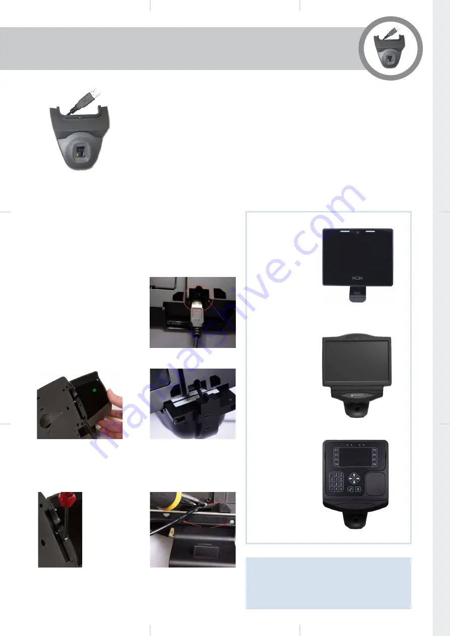
1.
GT10 Only
Feed USB cable through the
aperture in the back plate
before attaching module.
2.
Fit Module to Back Panel
Slide the Fingerprint Module
into the groove in the bottom
aperture of the Back Panel as
shown below.
RM-LUM-M320-IT/A
Installation Guide
Version 1.2 May 2020
Lumidigm Biometric
Reader Module
General
The RM-LUM-M320-IT/A uses
the Lumidigm Mercury sensor, an
optical biometric fingerprint module
that uses multispectral imaging
technology.
Module Power Loading
150mA @12V Terminal Power IN
Key features include
Verify (1:1) and Identify (1:N)
modes of operation
Finger Sensor sealed to IP65
Easy installation
Simple USB Connection
The biometric fingerprint reader is
housed in a module that slots on
to the terminal back panel and is
secured in position using a single
screw.
Fitting the Reader Module
This module can be used with the GT10 (RM-LUM-M320-A) or
IT51E and GT4 (RM-LUM-M320-IT) type terminals.
Ensure the terminal is powered down and then follow the
procedure below.
Note:
The RM-LUM-M320-IT/A reader can be
connected to any of the 6 USB ports found on
the IT51E/GT10 terminal front panel assembly
or any of the 4 USB ports found on the GT4
terminal front panel.
GT10 +
RM-LUM-M320-A
IT51E +
RM-LUM-M320-IT
GT4 +
RM-LUM-M320-IT
3.
Secure Module with Screw(s)
The module is secured using the single screw (IT51E
& GT4) or 3 screws (GT10) provided as shown. Screw
tension should be sufficient to hold module firmly but avoid
over tightening.
4.
Connect Module
Feed the USB cable through the bottom aperture in the Back
Panel and connect to an available USB port inside the unit.
GT10 Only.
Fit the 2
longer screws
at the front.


