286 | Using VisualRF
Dell PowerConnect W-AirWave 7.6 | User Guide
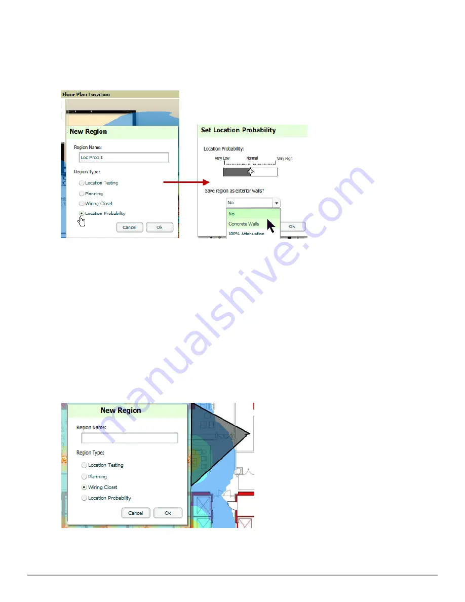
4. Move the location probability slider to the desired level, as shown on
Figure 212
.
Very Low
will decrease the
probability of a device being placed in that region by 20%.
Very High
will increase the probability of a device
being placed in that region by 20%.
Figure 212:
Adding a New Location Probability Region
5. Optionally, you can save the location region as the exterior walls. 100% attenuation can be selected to force
VisualRF to only place devices inside of the selected region. No device will ever be placed outside of the
probability region when 100% attenuation is selected. 100% attenuation is only recommended for tall buildings
where it is extremely unlikely that any user is located outside of the building. No heat map or attenuation grid is
calculated for devices outside of the 100% attenuation region.
Adding a Wiring Closet
To add a Wiring Closet to VisualRF, follow these steps:
1. In the
Edit
menu, select the
Draw Region
option.
2. Outline the desired region. Double click or press
Ctrl+click
to end the outline process.
3. Name the region, select a Region Type of
Wiring Closet
, and select
OK
, as shown in
Figure 213
.
Figure 213:
Adding a new Wiring Closet Region
Содержание PowerConnect W-AirWave 7.6
Страница 1: ...Dell PowerConnect W AirWave 7 6 User Guide ...
Страница 12: ...xii Dell PowerConnect W AirWave 7 6 User Guide ...
Страница 112: ...100 Configuring and Using Device Groups Dell PowerConnect W AirWave 7 6 User Guide ...
Страница 162: ...150 Discovering Adding and Managing Devices Dell PowerConnect W AirWave 7 6 User Guide ...
Страница 198: ...186 Using RAPIDS and Rogue Classification Dell PowerConnect W AirWave 7 6 User Guide ...
Страница 276: ...264 Creating Running and Emailing Reports Dell PowerConnect W AirWave 7 6 User Guide ...
Страница 324: ...312 Using VisualRF Dell PowerConnect W AirWave 7 6 User Guide ...
Страница 332: ...320 Index Dell PowerConnect W AirWave 7 6 User Guide ...


