SiME332106E
Field Settings for Outdoor Unit
Part 5 Field Settings and Test Operation
125
Wait until the LEDs are OFF before returning fasten terminals back to the compressor
terminals.
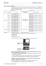
Minimum requirements to refer to the result on the inverter checker module:
Line (for RXYMQ4AVMK) or all 3 phases (for RXYMQ4-6AYFK) and neutral are
available, and
Inverter circuit is active. Check if the green LED “HBP” on the main PCB (for
RXYMQ4AVMK) or "HAP" on the inverter PCB (for RXYMQ4-6AYFK) is blinking
normally (approximately 1/second). If LED is OFF, need to exit the “standby mode” of
the inverter:
Disconnect and reconnect power supply control PCB, or
Forced thermostat ON condition, or
Make shortly set 2-6-1 (forced thermostat ON indoor), or
2-20-1 (manual refrigerant charge).
Once the LED is blinking on the PCB, change related setting immediately back to set
0 to deactivate related function.
Diode module generates the required 300 VDC (for RXYMQ4AVMK) or 500 VDC (for
RXYMQ4-6AYFK).
Cautions:
To stop the power transistor check mode, change setting to default 2-28-0.
Output to U/V/W will also stop when outdoor unit main PCB decides standby mode of
inverter circuit.
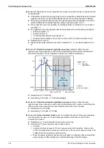
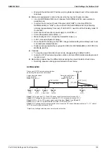
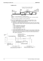
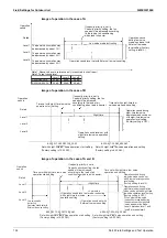
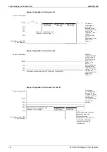
Below time graphs show the different steps during the power transistor check mode.
Switching sequence during power transistor check mode:
RXYMQ4AVMK
Check 1
: AC power input (L, N on X1M: power supply terminal block) around 220 V
Check 2
: DC voltage on inverter circuit capacitor (C+,C–) increases to around 310 V.
Check 3
: VDC = 1.42 × VAC power supply (calculation from
Check 1
and
Check 2
)
Check 4
: AC U/V/W 10 rps intermediate (at fasten U/V/W) around 10 V
Check 5
: DC voltage drop (discharge inverter circuit capacitor DC) check difference between “C+, C–” within 2
LED (V phase) brightness reduce till off.
*Note: Actual voltage value depends on meter characteristics.
Check 3
Check 2
Check 1
Frequency 10 rps
Power transistor check
mode activate;
Mode 2-28 set 0
Ѝ
1
VAC [U/V/W]
Power transistor check
mode activate;
Mode 2-28 set 1
Ѝ
0
VDC [C+/C–]
(310 VAC)
60 VAC
Check 4
Check 5
About 6 minutes
Power supply
OFF
VAC
L/N
VDC
C+/C–
VDC =
1.42 × VAC
VAC
U/V/W
Disconnect U/V/W from compressor before
performing the power transistor check.
VDC
C+/C–
Time
Содержание VRV RXYMQ-A Series
Страница 1: ...Service Manual RXYMQ A Series Heat Pump 50 60 Hz SiME332106E...
Страница 283: ...SiME332106E Check Part 6 Service Diagnosis 277 PCB and Circuit Diagram U V W L3B L2B L1B P1 P2 N32...
Страница 296: ...SiME332106E 290 Part 7 Appendix 1 Wiring Diagrams 291 1 1 Outdoor Unit 291 1 2 VRV Indoor Unit 293 Part 7 Appendix...
Страница 297: ...SiME332106E Wiring Diagrams Part 7 Appendix 291 1 Wiring Diagrams 1 1 Outdoor Unit RXYMQ4AVMK C 3D133942...
Страница 298: ...Wiring Diagrams SiME332106E 292 Part 7 Appendix RXYMQ4 5 6AYFK C 3D133944A...
Страница 303: ...SiME332106E Wiring Diagrams Part 7 Appendix 297 FXMQ40 50 63 80 100ARV1 3D127112 04 59...

