SiME332106E
Field Settings for Outdoor Unit
Part 5 Field Settings and Test Operation
123
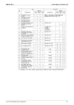
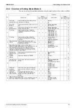
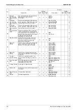
Mode 2-12:
Enable input “DTA104A61/62”
: enable the low noise function and/or power
consumption limitation. If the system needs to be running under low noise operation or under
power consumption limitation conditions when an external signal is sent to the unit, this
setting should be changed. This setting will only be effective when the optional external
control adaptor for outdoor unit (DTA104A61/62) is installed and the address set by DIP
switches on DTA104A61/62 corresponds to the address set on the outdoor unit(s) – set 2-.
Default value: 0.
To enable input from DTA104A61/62, change the item 2-12 to 1.
Mode 2-13:
AIRNET address
.
When an AIRNET system will be used, outdoor unit needs an AIRNET address.
Also to facilitate the recognition of a system in the map lay out of the service checker type
III, set each system a unique address between 1 and 63.
When duplicating of AIRNET address,
UC
error code will appear on central control.
Mode 2-18:
Fan high external static pressure mode
setting
Fan revolutions will be adjusted automatically according to external static pressure.
Default value: 0. Judge external static pressure level during operation check and every
cooling restart standby.
Set 1: Judge external static pressure level during operation check.
Set 2-4: Forced external static pressure level 0-2.
Mode 2-21:
Refrigerant recovery / vacuuming
.
Default value: 0. Recovery mode not active.
Set 1: outdoor and indoor electronic expansion valves are opened fully (except EV3 for
PCM vessel). Compressor(s) do not operate.
All controllers show “Test” and LED operation-ON, but indoor and outdoor fan do not
operate.
Outdoor segment display indicates
t01
.
By opening indoor and outdoor electronic expansion valves there is a free pathway to
reclaim remaining refrigerant out by using a refrigerant recovery unit to a refrigerant
recovery bottle.
Prior to launch the recovery mode, ensure:
To vacuum all lines between service hoses – refrigerant recovery unit and recovery
bottle.
Weight the refrigerant recovery bottle to know recovered amount when refrigerant
recovery function is terminated.
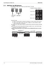
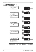
To end the refrigerant recovery mode, press BS3 button once. The 7 segment display
returns to normal (all off).
Mode 2-22:
Selection automatic night-time low noise operation
level. The outdoor can
switch automatically to a pre-set night-time low noise operation level during night-time
judgment.
Default value: 0. Auto night-time low noise operation not active.
Set 1: use level 1.
Set 2: use level 2.
Set 3: use level 3.
Set period: refer to set the item 2-26 for start time and the item 2-27 for end time.
Mode 2-23:
Eco mode invalid
setting
Eco mode becomes invalid by this setting.
When this configuration is set, it is not possible to turn Eco mode ON/OFF using external
control adaptor or other setting.
Default value: 0, Eco mode is active.
Te fix control 2-23: 1 or 3
Tc fix control 2-23: 2 or 3
Содержание VRV RXYMQ-A Series
Страница 1: ...Service Manual RXYMQ A Series Heat Pump 50 60 Hz SiME332106E...
Страница 283: ...SiME332106E Check Part 6 Service Diagnosis 277 PCB and Circuit Diagram U V W L3B L2B L1B P1 P2 N32...
Страница 296: ...SiME332106E 290 Part 7 Appendix 1 Wiring Diagrams 291 1 1 Outdoor Unit 291 1 2 VRV Indoor Unit 293 Part 7 Appendix...
Страница 297: ...SiME332106E Wiring Diagrams Part 7 Appendix 291 1 Wiring Diagrams 1 1 Outdoor Unit RXYMQ4AVMK C 3D133942...
Страница 298: ...Wiring Diagrams SiME332106E 292 Part 7 Appendix RXYMQ4 5 6AYFK C 3D133944A...
Страница 303: ...SiME332106E Wiring Diagrams Part 7 Appendix 297 FXMQ40 50 63 80 100ARV1 3D127112 04 59...

