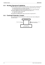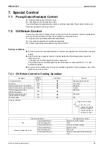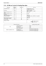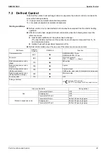
Outline of Control (Indoor Unit)
SiME332106E
70
Part 4 Functions and Control
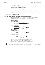
8.2.2 With Optional Infrared Presence/Floor Sensor
The thermostat ON/OFF condition is determined by the difference between the remote
controller set temperature and the detected temperature around people.
Normal operation
Cooling operation
Heating operation
Dry operation
When Tro ≤ 24.5°C
When Tro > 24.5°C
: Description of symbols
ΔT = Detected room temperature – Remote controller set temperature
Tro: Detected room temperature at the start of dry operation
Tr: Determined by the room temperature detected by the thermistor
Control range of temperature around people
When the floor temperature is very low, operation using the temperature around people may
cause the suction air temperature to operate outside of use range.
To avoid the above condition, a limit based on the suction air temperature is set for the use
range of the temperature around people.
Cooling operation
When the floor temperature is lower than suction air thermistor detection temperature (R1T),
R1T will be treated as the control target temperature for operation.
When the temperature around people is 15°C or lower, R1T will be treated as the control
temperature for operation.
Heating operation
When the floor temperature is higher than suction air thermistor detection temperature
(R1T), R1T will be treated as the control target temperature in operation.
When the temperature around people is 33°C or higher, R1T will be treated as the control
temperature for operation.
Thermostat OFF
Normal operation
(Thermostat ON)
Δ
T ≤
–1.0°C
Δ
T ≥
+
1.0°C
Thermostat OFF
Normal operation
(Thermostat ON)
T
1.0°C
T
–1.0°C
Thermostat OFF
Dry operation
Tr
<
Tro – 1.0°C
Tr
>
Tro + 1.0°C
Thermostat OFF
Dry operation
Tr
<
Tro – 1.5°C
Tr
>
Tro + 0.5°C
Содержание VRV RXYMQ-A Series
Страница 1: ...Service Manual RXYMQ A Series Heat Pump 50 60 Hz SiME332106E...
Страница 283: ...SiME332106E Check Part 6 Service Diagnosis 277 PCB and Circuit Diagram U V W L3B L2B L1B P1 P2 N32...
Страница 296: ...SiME332106E 290 Part 7 Appendix 1 Wiring Diagrams 291 1 1 Outdoor Unit 291 1 2 VRV Indoor Unit 293 Part 7 Appendix...
Страница 297: ...SiME332106E Wiring Diagrams Part 7 Appendix 291 1 Wiring Diagrams 1 1 Outdoor Unit RXYMQ4AVMK C 3D133942...
Страница 298: ...Wiring Diagrams SiME332106E 292 Part 7 Appendix RXYMQ4 5 6AYFK C 3D133944A...
Страница 303: ...SiME332106E Wiring Diagrams Part 7 Appendix 297 FXMQ40 50 63 80 100ARV1 3D127112 04 59...

