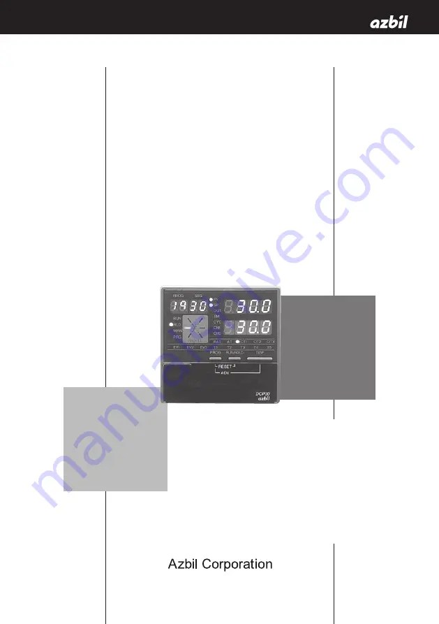
Azbil DCP31 Скачать руководство пользователя страница 1

Thank you for purchasing an Azbil 

Corporation product.
This manual contains information 

for ensuring the correct use of this 

product. It also provides necessary 

information for installation, main-

tenance, and troubleshooting.
This manual should be read by 

those who design and maintain 

equipment that uses this product. 

Be sure to keep this manual nearby 

for handy reference.

DCP31 

DIGITRONIK 

Digital Program  

Controller

User's Manual

No. CP-UM-1757E

(Not for use in Japan)

Содержание DCP31

Страница 1: ...It also provides necessary information for installation main tenance and troubleshooting This manual should be read by those who design and maintain equipment that uses this product Be sure to keep t...

Страница 2: ...anual is free from inaccuracies and omissions If you should find an error or omission please contact the azbil Group In no event is Azbil Corporation liable to anyone for any indirect special or conse...

Страница 3: ...Supply voltage 100 to 240 Vac operating supply voltage 90 to 264 Vac Frequency 50 60 Hz Power consumption 30 VA max EQUIPMENT CONDITIONS Do not use this device near flammable fluids or vapors Under s...

Страница 4: ...roduct to prevent injury to the operator and others and to prevent damage to property Be sure to observe these safety precautions WARNING Warnings are indicated when mishandling this product might res...

Страница 5: ...t cause fire or faulty operation Do not block ventilation holes Doing so might cause fire or faulty operation Do not allow lead clippings chips or water to enter the DCP31 case Doing so might cause fi...

Страница 6: ...semble or heat batteries Store batteries in low temperature dry locations Failure to observe the above cautions may cause batteries to emit heat or split or battery fluid to leak Store batteries out o...

Страница 7: ...ries are included in the package After unpacking handle the DCP31 and its accessories taking care to prevent damage or loss of parts If an inconsistency is found or the package contents are not in ord...

Страница 8: ...er When you have finished mounting and wiring the controller fix cellophane adhesive tape on the corners of the filter and pull in the direction of the arrow to peel off the protective film Handling P...

Страница 9: ...n trouble shooting and specifications SLP P30 Smart Loader Package for DCP31 32 DIGITRONIK Digital Program Controller User s Manual Manual No CP UM 1759JE This manual is written in both Japanese and E...

Страница 10: ...controller This chapter is required reading for designers of control systems using the DCP31 Chapter 6 OPERATION This chapter describes how to switch the basic display states of the DCP31 and select a...

Страница 11: ...y CPL communications 1 4 1 5 Model Numbers 1 5 Model selection guide 1 5 Chapter 2 NAMES FUNCTIONS OF PARTS 2 1 2 1 Structure 2 1 2 2 Console 2 2 Basic display state 2 2 Display 2 2 Keys 2 5 Functions...

Страница 12: ...8 Connecting control outputs outputs 1 2 4 9 Relay output 0D 4 9 Current output 5G 4 9 Position proportional output 2G 4 10 Voltage output 6D 4 10 Heat cool output 3D 4 11 Heat cool output 5K 4 11 4...

Страница 13: ...mmer 5 22 5 5 Input Processing Functions 5 23 5 6 Output Processing Functions 5 24 Control output 5 24 SP output 5 28 Auxiliary output 5 29 Chapter 6 OPERATION 6 1 6 1 Turning the Power ON 6 1 6 2 Swi...

Страница 14: ...setup data settings 7 54 Table data settings T B L 7 63 Description of table data settings 7 64 Constant value operation data settings C N S t 7 66 Chapter 8 PROGRAM SETUP 8 1 8 1 Program Setup 8 1 Ho...

Страница 15: ...he basic display state 9 6 The controller does not change to FAST mode by pressing in the basic display state 9 6 The controller does not change to MANUAL mode by pressing in the basic display state 9...

Страница 16: ...pressing in program setup state 9 10 Program deletion cannot be confirmed by pressing while entering pattern items in program setup state 9 10 The program cannot be copied by pressing in the basic di...

Страница 17: ...n to when handling the DCP31 Note Notes indicate useful information that the user might benefit by knowing These icons represent keys on the DCP31 s console Combinations of icons like these indicate t...

Страница 18: ......

Страница 19: ...roportional output current output voltage time proportional output and heat cool output On models other than heat cool control output you can also choose neural net based auto tuning and smart tuning...

Страница 20: ...ol Auto tuning Neuro Fuzzy Forward reverse action ON OFF control SP limit SP bias Output change limitter Upper lower limitter SP output Outputs Current Relay Voltage Position proportional Heat cool Ev...

Страница 21: ...ogram patterns Parameters SP Time Program No 19 Number of segments 8 SP Time Program No 3 Number of segments 15 Time Program No 2 Number of segments 19 SP Time Program No 1 Number of segments 6 15 13...

Страница 22: ...the CPL communications Controller Peripheral Link Azbil Corporation host communication protocol network Handling Precautions On the 3 lead RS 485 interface the Azbil Corporation CMC10L001A000 can be u...

Страница 23: ...between current output and voltage output 0 One input channel AS Free power supply 90 to 264 Vac 00 No auxiliary output 01 1 auxiliary output 02 2 auxiliary outputs 0 External switch inputs 4 time ev...

Страница 24: ......

Страница 25: ...xternal switch inputs 4 and auxiliary outputs options Terminal for connecting external switch inputs 8 options time event outputs options and CPL communications options The add on terminal base is pro...

Страница 26: ...Program No display In the basic display state this display indicates the currently selected program No In the program setup state this display indicates the program No currently being set up During co...

Страница 27: ...ts in the MANUAL mode and goes out in the AUTO mode PRG Lights in the program setup state Otherwise this LED is out Upper display In the basic display state displays PV and other values In the paramet...

Страница 28: ...ights during time display Otherwise this LED is out CYC Lights during cycle display Otherwise this LED is out CH1 Out CH2 Out Event LEDs EV1 EV2 EV3 In the basic display state or parameter setup state...

Страница 29: ...ce the program in RUN HOLD FAST modes PROG DISP To run the program fast in RUN HOLD modes FUNC To execute manual operation in AUTO mode A M To execute automatic operation in MANUAL mode To start auto...

Страница 30: ...lay state PARA To selects setup group To end parameter setup DISP PARA key Assignment item setup To start changing assignment item setting values in basic display state PARA To move to next item by as...

Страница 31: ...in descending order FUNC To end program setup programming DISP Program copy To start program copy in basic display state PROG To change the copy destination program No To execute program copy while se...

Страница 32: ...RA with FUNC held down in the basic display state to move to se lection of the setting group major items in the parameter setup state FUNC PROG Program setup programming keys Press PROG with FUNC held...

Страница 33: ...UTO mode in the basic display state to move to the general reset confirmation screen Loader jack This jack is for connecting the loader Objects other than the loader plug should not be inserted into t...

Страница 34: ...1600 T CC 8 T44 200 0 to 300 0 300 to 700 B PR30 6 9 B18 0 to 1800 0 to 3300 R PR13 10 R16 0 to 1600 0 to 3100 S PR10 11 S16 0 to 1600 0 to 3100 W WRe5 26 12 W23 0 to 2300 o to 4200 W WRe5 26 13 W14...

Страница 35: ...500 0 40 F01 0 00 to 100 00 0 0 to 200 0 JIS 89 J Pt100 48 P50 200 0 to 500 0 300 to 900 49 P46 200 0 to 200 0 300 to 400 50 P32 100 0 to 150 0 150 0 to 300 0 51 P36 50 0 to 200 0 50 0 to 400 0 52 P3...

Страница 36: ...t readout C of codes F01 and P01 The PV lower limit alarm does not occur with code F50 However note that the PV lower limit alarm occurs at a discon nection when input has been downscaled when input i...

Страница 37: ...proof cover set sold separately 81446087 001 Hard dust proof cover set sold separately 81446083 001 Terminal cover set sold separately 81446084 001 96 96 B B 37 78 4 110 5 A A 90 2 91 5 Back plate Ad...

Страница 38: ...the operating temperature range 0 to 50 C particularly when mounting vertically or during multiple mounting 46 46 96 x N 1 96 x N 4 N number of units installed Panel cutout dimensions Panel cutout di...

Страница 39: ...e controller case Doing so might cause fire or faulty operation Mounting locations Avoid installing the DCP31 in the following locations Locations outside of the operating temperature range 0 to 50 C...

Страница 40: ...a CR filters for fast rising noise Recommended CR filter Azbil Corporation Model No 81446365 001 Provision of a varister for noise with a high wave height Recommended varister Azbil Corporation Model...

Страница 41: ...by lower mounting bracket 1 first Handling Precautions To secure the controller tighten the screw on the mounting bracket supplied until there is no more play and then tighten a further full turn Take...

Страница 42: ...3 6 Chapter 3 MOUNTING Keep the mounting angle to within 10 from the horizontal at both the controller rear top and bottom Lift up from rear by 10 max Pull down from rear by 10 max...

Страница 43: ...ty operation Inputs to the current input terminals and on the DCP31 should be within the current and voltage ranges listed in the specifications Failure to do so might cause electric shock or faulty o...

Страница 44: ...e DCP31 s I O parallel connection in case of input to an A D converter or analog scanner read data may fluctuate To prevent this adopt one of the following measures 1 Use a low speed integrating type...

Страница 45: ...able or equivalent product This is generally referred to twisted shielded cable for instruments The following cables are recom mended Fujikura Ltd 2 core IPEV S 0 9 mm2 x 1P 3 core ITEV S 0 9 mm2 x 1T...

Страница 46: ...sure to use round crimped terminals to prevent the lead from coming loose from the terminal When wiring with crimped terminals take care to prevent con tact with adjacent terminals The recommended ti...

Страница 47: ...ds on the standard terminal base The lead draw out directions are the same when using the add on terminal base Standard terminal base Lead draw out direction Lead draw out direction 34 33 32 31 30 29...

Страница 48: ...ower leads together or pass them through the same piping or wiring duct Ground When it is difficult to ground shielded cable prepare a separate ground terminal earth bar Ground type 100 max Ground cab...

Страница 49: ...tput Auxiliary output Relay Relay 4 to 20 mA voltage 4 to 20 mA voltage 4 to 20 mA Output 1 Output 2 Auxiliary output 1 Auxiliary output 2 External switch input RSW Current input Input Resistance temp...

Страница 50: ...t input terminals and may cause faulty operation Take care of polarities when wiring inputs Use only shielded cable for wiring inputs When using a thermocouple input prevent air blasts from coming int...

Страница 51: ...a bleeder resistor to allow current flow of the minimum relay switching input 100 mA min Current output 5G Connect as follows Handling Precautions 4 to 20 mAdc and 0 to 20 mAdc can be selected in set...

Страница 52: ...t result in faulty controller operation caused by electrical noise when the motor is started up When controlling without motor feedback with variable param eter M C set to 2 terminals need not be conn...

Страница 53: ...tained matched to the conditions of the SSR in use and load Factory setting general purpose SSR voltage value 11 12 13 14 15 16 Load Power supply Load Power supply Output 1 Contact rating resistive lo...

Страница 54: ...only 2G 3D 5K auxiliary outputs Auxiliary output 1 is not provided for 2G 3D and 5K outputs Handling Precautions 4 to 20 mA dc and 0 to 20 mA dc can be selected in setup data C 9 0 Use shielded cable...

Страница 55: ...allow current flow of the minimum relay switching input 10 mA min 10 8 9 6 7 4 5 EV1 1a EV2 1a EV3 1a1b Load Power supply Load Power supply Load Power supply Standard terminal base Contact rating res...

Страница 56: ...aulty open collector output The DCP31 does not contain a short circuit prevention circuit When connecting to a semiconductor load such as a program mable controller sequencer select a module whose cur...

Страница 57: ...t minimum switching capability with respect to the contact current and open voltage of the DCP31 When using a semiconductor e g open collector as a no voltage contact use a semiconductor whose contact...

Страница 58: ...ecautions Do not connect to the SDC20 21 or SDC30 31 series in paral lel Doing so might damage the external switch inputs of the SDC20 21 or SDC30 31 24 21 25 12 Vdc 12 Vdc 48 41 12 Vdc 12 Vdc Standar...

Страница 59: ...re that different addresses are set for each slave station Connect terminating resistors a total of 4 in the case of a 5 lead connection to both ends of the transmission line Use terminators having a...

Страница 60: ...is sion line Grounding of the shielded FG terminal should be carried out at only one end and not both ends 57 58 59 60 61 SDA SDB RDA RDB SG FG 57 58 59 60 61 SDA SDB RDA RDB RDA RDB SDA SDB SG FG SG...

Страница 61: ...his connection the Azbil Corporation CMC10L001A000 can be used as a host sta tion converter When there are only three RS 485 terminals terminals marked are wired internally 57 58 59 60 61 SDA SDB RDA...

Страница 62: ...17 18 4 5 6 7 8 9 10 49 56 32 33 34 21 25 41 48 57 61 Input 1 full multiple input PV supported Output 1 relay current voltage output Output 2 relay current voltage output auxiliary output Output 3 au...

Страница 63: ...10 49 56 31 32 33 34 21 25 41 48 57 61 Input 1 full multiple input PV supported Output 1 control output 1a relay x 2 Motor feedback input Output 3 auxiliary output Event output 1 relay output 1a Event...

Страница 64: ......

Страница 65: ...table data Data e g SP PID of constant value operation SP and time data Events 1 to 3 data Time events 1 to 5 time data PID set No data for use in control G Soak ON OFF data PV START ON OFF data Cycl...

Страница 66: ...ramp rising ramp rising tendency Previous segment SP setting value current segment SP setting value Falling ramp falling ramp falling tendency Previous segment SP setting value current segment SP set...

Страница 67: ...ndby Events function as follows when event standby has been set to ON If the controller is in the state in the figure when changing from the READY to the RUN mode and after restoring the power operati...

Страница 68: ...disable the event set in the previous segment from a certain segment onwards Direct action events Upper limit value of event setting Reverse action events Lower limit value of event setting Note howev...

Страница 69: ...V MV MV reverse H EV MFB MFB reverse H SP EV PV Deviation direct H H EV EV SP PV Absolute value deviation direct H EV SP SP direct H EV MV MV direct H EV MFB MFB direct H H EV EV SP PV Absolute value...

Страница 70: ...FAST END G Soak standby MANUAL Auto tuning executing Constant value operation MFB estimated position control sum of all alarms PV range alarm Controller alarms Low battery voltage Console setup in pr...

Страница 71: ...vance The event ON delay is disabled and a delay is not applied Program end When the DCP31 automatically including ADV reaches the READY mode from program operation status RUN HOLD FAST without perfor...

Страница 72: ...d OFF time are not set output is OFF See segment 3 in the figure Setting only the OFF time without an ON time is not possible See segment 3B in the figure Setting an ON time to be greater to or equal...

Страница 73: ...in the case of G Soak standby output becomes ON from the G Soak standby state and the ON time is started at completion of the G Soak standby time The output time G Soak time OFF time See segment 8 in...

Страница 74: ...6 7 8 9 10 11 12 13 14 15 T1 ON OFF ON OFF ON OFF ON OFF ON OFF ON OFF ON OFF ON T2 OFF ON ON OFF OFF ON ON OFF OFF ON ON OFF OFF ON ON T3 OFF OFF OFF ON ON ON ON OFF OFF OFF OFF ON ON ON ON T4 OFF OF...

Страница 75: ...hods cannot be set simultaneously Note When setup data C 1 1 is set to 1 PID items in the program setup are not displayed By designation of PID set segment the PID set No is set for each segment and c...

Страница 76: ...G Soak standby state even if G Soak is set to ON The G Soak standby state can also be canceled by external switch output The following cancel conditions can be selected by the setup date C 5 2 to C 5...

Страница 77: ...repeating operation from the No 1 segment of the program pattern to the final set segment for a preset number of cycles The number of cycles can be set up to 9999 When a number of cycles n is set the...

Страница 78: ...n a stepped manner during link operation When cycle operation has been set the pat tern link function works after cycle operation has ended After pattern link operation ends operation begins from the...

Страница 79: ...No 1 to 19 Constant value operation Operation is carried out according to SP or events set in the con stant value operation data Time events 1 to 5 turn OFF READY AUTO MANUAL AUTO MANUAL AUTO MANUAL...

Страница 80: ...that progress of program operation stops in the same way as the HOLD mode when the controller is in the G Soak Guar antee Soak standby state HOLD In this mode the program is held Progress of program...

Страница 81: ...ation AUTO In this mode program operation is automatic MV output is active according to controller control However note that when programmer functions are selected on 5G output models SP output is act...

Страница 82: ...am shows mode transition operation Note When shifting between the AUTO and MANUAL modes the modes in the square frames can be shifted between Switching between program operation and constant value ope...

Страница 83: ...hifting to the HOLD mode from the RUN or FAST modes The HOLD mode is not available in the constant value operation mode RESET This operation involves shifting to the READY mode from the RUN HOLD FAST...

Страница 84: ...AUTO mode by external switch inputs or communications the display changes to the basic display state even in the parameter setup or program setup states Program end When operation progresses in the RU...

Страница 85: ...ns Key Switch Com muni cations Key Switch Com muni cations Program operation READY RUN HOLD FAST END Constant value operation READY RUN Operation Original mode MANUAL to MANUAL mode AUTO to AUTO mode...

Страница 86: ...heat cool PID control and 3 position proportional is also possible depending on the type of output supported by the model of DCP31 In the MANUAL mode the MV can be incremented or decrement ed in the b...

Страница 87: ...limit alarm Square root extraction Temperature unit range Linearization approximation Digital filter Bias PV1 DC current and voltage Setting Setup data C07 Setting Setup data C03 thermocouple and res...

Страница 88: ...ion of PID control operation PID control operation Output change limitter Output upper lower limit limitter Manipulated variable MV1 Output 1 AT execution MV in READY mode Preset manual value Manual M...

Страница 89: ...et manual value Manual MV AT operation ON OFF control operation Setting PID parameters p 1 d RE PID parameters dP di dd PID parameters br Setting Variable parameters OTL Setting PID parameters OL OH S...

Страница 90: ...MV Preset manual value MFB automatic adjustment MV at over range AT operation Output 1 open side relay Output 1 closed side relay Setting Variable parameters 1 OUT rpi d Setting PID parameters p 1 d R...

Страница 91: ...Setting Setup data C 14 C 15 Setting Variable parameter DI FF Setting PID parameters OL OH odd numbered PID sets Setting Setup data C 16 relay voltage output Setting Variable parameter CY 1 voltage o...

Страница 92: ...t models SP output is processed is as follows MANUAL mode Main output types Upper lower limit scaling SP1 output Output 1 READY mode Upper lower limit scaling Manual SP1 MV in READY mode Current outpu...

Страница 93: ...utput type SP and deviation When auxiliary output type is NOP When auxiliary output type is set to MFB on non 2G output models When auxiliary output type is set to MV by programmer function on 5G outp...

Страница 94: ......

Страница 95: ...if in basic display state in AUTO mode Power ON NO YES Start of operations Check start of general reset Press key RAM backup normal ENT Continuation of program operation constant value operation mode...

Страница 96: ...ent LEDs Output states of events 1 to 3 time events 1 to 5 Supplementary explanation In the program operation mode READY indicates the currently selected program segment No Displays other than READY i...

Страница 97: ...play 5 Display 6 Display 7 Display 1 repeated Display 1 The digit to which SP values can be entered blinks in the MANUAL mode when programmer functions are selected Display 2 The digit to which SP val...

Страница 98: ...in setup settings Select either remaining segment time or total operating time in setup settings as the details whose time is to be displayed Program No Segment No Pattern tendency Motor valve openin...

Страница 99: ...lected Either of h min or min s is selected as the time unit in setup settings Select either remaining segment time or total operating time in setup set tings as the details whose time is to be displa...

Страница 100: ...epeated 3D 5K Display 1 Display 2 Display 4 Display 1 repeated Display 1 The digit to which SP values can be entered blinks in the MANUAL mode when controller functions are selected Display 2 The digi...

Страница 101: ...t models output catalog No appended with 2 G Display 4 This display is exclusive to heat cool output models output catalog No appended with 3 D or 5 K Motor valve opening Output state of events 1 to 3...

Страница 102: ...display reverts to 19 after 1 Handling Precautions Both already set or non set program Nos can be selected The program No cannot be selected when selecting the program No by external switch input The...

Страница 103: ...ns FAST Rising edge PV start Rising edge AUTO MANUAL Rising falling edge AT start stop Rising falling edge G Soak cancel by OR conditions Status G Soak cancel by AND conditions Status Direct reverse a...

Страница 104: ...h G Soak cancel by AND conditions G Soak standby is can celed when the external switch turns ON or when the PV enters the G Soak width When the external switch turns ON by direct reverse action switch...

Страница 105: ...ON ON ON OFF OFF RSW11 8 OFF OFF OFF OFF OFF OFF OFF OFF ON ON RSW12 10 OFF OFF OFF OFF OFF OFF OFF OFF OFF OFF Program No Selection 0 1 2 3 4 5 6 7 8 9 External Switch No Weighting State RSW8 1 OFF...

Страница 106: ...be sure to observe timings 1 to 4 in the following diagram PV start operation also must conform to RUN operation 1 The time from fixing of the selected No up to the rising edge of the RUN signal is 0...

Страница 107: ...carried out more reliably if a margin is added to the minimum time for the above read times READY RUN State of No different from that selected State of No different from that selected State of select...

Страница 108: ...UAL mode can be selected by setup parameter C 15 set ting When shifting from the MANUAL to the AUTO mode output is bumpless However when the total time for the PID parameter of the PID set in use is s...

Страница 109: ...involves calculating the downtime and critical sensitivity of the line according to two limit cycles and PID values according to suitable characteristic equations for each and automatically writing th...

Страница 110: ...Precautions Auto tuning will not function properly unless the control target is connected The time from start to end of auto tuning varies according to the control target When auto tuning is executed...

Страница 111: ...of setting group major item the setting group is displayed on the upper display and the lower display goes out If you press PARA or the setting group display changes in order If you press ENT when the...

Страница 112: ...ble parameter L O C is 1 2 or 4 Table data T B L This parameter is not displayed when variable parameter L O C is 2 or 4 Constant value operation data C N S T This parameter is not displayed when vari...

Страница 113: ...it state and the new setting value is stored to internal memory To cancel changing of setting values press PARA or DISP When PARA is pressed the value stops blinking and the display returns to its nor...

Страница 114: ...items Setting value blinking Basic Display State Change setting value ENT key ENT key PARA key DISP key ENT key PARA key key key key key key key key key DISP key key key key key Individual items mino...

Страница 115: ...the following order FUNC PARA selection of setting group individual item matrix How to register assignment items To register an assignment item add the following base correspond ing to the setting gro...

Страница 116: ...o 1 of C 0 1 to setup data radical 4500 56 C 5 6 PARA assignment item 2 1511 This is produced by adding item No 11 of P 2 to PID parameter radical 1500 57 C 5 7 PARA assignment item 3 2503 This is pro...

Страница 117: ...these items are displayed blink ing the setting values can be changed by and ENT stores data to memory Items for reference These are displayed at all times Basic Display State Max 8 items ENT key ENT...

Страница 118: ...settings disabled 2 Display of parameter settings and program settings disabled 3 Use of operation keys disabled 4 Display of parameter settings and program settings displayed and use of operation ke...

Страница 119: ...models is dis played and setting is not possible 10 S T Smart tuning method selection CH1 0 0 Smart tuning is disabled 1 The brake value is fixed to inhibit over shoot 2 Overshoot is inhibited while...

Страница 120: ...X 10 X 3 120 X 10 X Note When setup data C 6 4 setting is 1 program time unit min s the FAST factor is 10 X for settings 2 and 3 21 d i f f ON OFF control differential 5 U 0 to 1000 U Note This setti...

Страница 121: ...etting is not possible 26 d V h 3 position control deviation upper limit 5 U 27 H Y L 3 position control lower limit hysteresis 5 U 28 H Y H 3 position control upper limit hysteresis 5 U 29 C Motor co...

Страница 122: ...n models other than 2G output mod els is displayed and setting is not possible Description of variable parameter settings L O C key lock 0 Key lock disabled 1 Display of setup data settings disabled 2...

Страница 123: ...ogram protect 0 Changing program settings enabled 1 Changing program settings disabled When P R T C is set to 1 the following keys are disabled Basic display state PROG program copy FUNC CLR DISP gene...

Страница 124: ...nitialization ON OFF and conditions can be selected by the R P I D setting S t smart tuning method selection 0 Smart tuning is disabled 1 The brake value is fixed to inhibit overshoot 2 Overshoot is i...

Страница 125: ...l the PID con stant These constants are set automatically during AT execution and is memorized They can also be set and changed independently In particular on 2G output models suppressing changes in M...

Страница 126: ...ife The factory setting is 5 Use this as a guideline and take the con trol results and motor service life into consideration when setting the dead zone Heat cool control dead zone 100 to 50 Heat cool...

Страница 127: ...V 50 the heat side PID set is switched to When MV 50 the cool side PID set is switched to Note 4 PID set selection is carried out by setting value and external switch Dead zone Output heat Output cool...

Страница 128: ...ST and END modes State Heat side Output Cool side Output MV 1 OFF 0 0 ON 100 0 0 0 2 OFF 0 0 OFF 0 0 50 0 3 ON 100 0 OFF 0 0 100 0 Handling Precautions Even in 3 position control output is time propor...

Страница 129: ...ng and estimated MFB value So set the closed side relay to ON at all times when output MV 0 0 and the open side relay to ON at all times when MV 100 0 to set the motor to a fully open or fully closed...

Страница 130: ...closed side and the MFB count value is displayed on the lower display When the count has stabilized fully closed adjustment is completed and the count value is written to C L C A O P is displayed on t...

Страница 131: ...less than 5 s MFB disconnected alarm A L 1 0 A L 1 1 occurs continu ously or frequently The time taken for the MFB count to stabilize exceeds 5 min Faulty wiring of MFB or switching relay However note...

Страница 132: ...0 MFB direct 11 MFB reverse 12 to 49 NOP Time events 50 Time event 51 to 99 NOP Controller status events 100 RUN HOLD FAST END 101 READY 102 RUN 103 HOLD 104 FAST 105 END 106 G Soak standby 107 MANUAL...

Страница 133: ...y after power is restored and in the READY mode When the event type setting is 50 is displayed and setting is not possible 3 H Y S 1 Event 1 hysteresis 5 0 to 200 U when event type is neither MV nor M...

Страница 134: ...reverse 12 to 49 NOP Time events 50 Time event 51 to 99 NOP Controller status events 100 RUN HOLD FAST END 101 READY 102 RUN 103 HOLD 104 FAST 105 END 106 G Soak standby 107 MANUAL 108 Auto tuning ex...

Страница 135: ...y after power is restored and in the READY mode When the event type setting is 50 is displayed and setting is not possible 7 H Y S 2 Event 2 hysteresis 5 0 to 200 U when event type is neither MV nor M...

Страница 136: ...reverse 12 to 49 NOP Time events 50 Time event 51 to 99 NOP Controller status events 100 RUN HOLD FAST END 101 READY 102 RUN 103 HOLD 104 FAST 105 END 106 G Soak standby 107 MANUAL 108 Auto tuning ex...

Страница 137: ...r MFB Note When the event type setting is 50 is displayed and setting is not possible 12 D L 3 Event 3 ON delay time 0 0 to 3600 s 13 T T Time event type 0 0 T1 to T5 are all time events 1 T1 is a seg...

Страница 138: ...MFB reverse 12 to 49 NOP Time events 50 Time event 51 to 99 NOP Controller status events 100 RUN HOLD FAST END 101 READY 102 RUN 103 HOLD 104 FAST 105 END 106 G Soak standby 107 MANUAL 108 Auto tuning...

Страница 139: ...after power is restored and in the READY mode When the event type setting is 50 is displayed and setting is not possible 19 H y t 1 T1 event hysteresis 5 0 to 200U when event type is neither MV nor M...

Страница 140: ...MFB reverse 12 to 49 NOP Time events 50 Time event 51 to 99 NOP Controller status events 100 RUN HOLD FAST END 101 READY 102 RUN 103 HOLD 104 FAST 105 END 106 G Soak standby 107 MANUAL 108 Auto tuning...

Страница 141: ...after power is restored and in the READY mode When the event type setting is 50 is displayed and setting is not possible 23 H y t 2 T2 event hysteresis 5 0 to 200 U when event type is neither MV nor...

Страница 142: ...MFB reverse 12 to 49 NOP Time events 50 Time event 51 to 99 NOP Controller status events 100 RUN HOLD FAST END 101 READY 102 RUN 103 HOLD 104 FAST 105 END 106 G Soak standby 107 MANUAL 108 Auto tuning...

Страница 143: ...after power is restored and in the READY mode When the event type setting is 50 is displayed and setting is not possible 27 H y t 3 T3 event hysteresis 5 0 to 200U when event type is neither MV nor M...

Страница 144: ...MFB reverse 12 to 49 NOP Time events 50 Time event 51 to 99 NOP Controller status events 100 RUN HOLD FAST END 101 READY 102 RUN 103 HOLD 104 FAST 105 END 106 G Soak standby 107 MANUAL 108 Auto tuning...

Страница 145: ...after power is restored and in the READY mode When the event type setting is 50 is displayed and setting is not possible 31 H y t 4 T4 event hysteresis 5 0 to 200U when event type is neither MV nor M...

Страница 146: ...FB reverse 12 to 49 NOP Time events 50 Time event 51 to 99 NOP Controller status events 100 RUN HOLD FAST END 101 READY 102 RUN 103 HOLD 104 FAST 105 END 106 G Soak standby 107 MANUAL 108 Auto tuning...

Страница 147: ...after power is restored and in the READY mode When the event type setting is 50 is displayed and setting is not possible 35 H y t 5 T5 event hysteresis 5 0 to 200 U when event type is neither MV nor...

Страница 148: ...irect operating point 500 C hysteresis 10 C and standby ON are set When the mode changes from READY to the RUN mode at PV 550 C the controller enters the standby state so event output is turned OFF St...

Страница 149: ...output models is displayed for items O L and O H and setting is not possible When I setting is not 0 is displayed for R E and setting is not possible When variable parameter S T setting is 0 smart tu...

Страница 150: ...vershoot or hunting more likely to occur Use of the controller on a motor or actuator shortens the controller s life Do not set the proportional band P D P to too small a value Decreasing the reset ti...

Страница 151: ...integration no longer func tions This prevents reset wind up that occurs when the PV has not risen for a long time Manual reset R E is a setting for eliminating offset that occurs during proportional...

Страница 152: ...Reset time PID set 6 0 53 D 6 Rate time PID set 6 0 54 O L 6 MV lower limit PID set 6 0 0 55 O H 6 MV upper limit PID set 6 100 0 56 R E 6 Manual reset PID set 6 50 0 57 B R 6 Brake PID set 6 0 58 D...

Страница 153: ...set time PID set 7 120 70 D D 7 Disturbance inhibit rate time PID set 7 0 71 P 8 Proportional band PID set 8 100 0 72 1 8 Reset time PID set 8 0 73 D 8 Rate time PID set 8 0 74 O L 8 MV lower limit PI...

Страница 154: ...When the input 1 range type is linear is displayed and setting is not possible 3 C 0 3 Input 1 range type 0 0 to 73 0 to 20 Thermocouple 32 to 40 48 to 56 Resistance temperature detector 64 to 73 Lin...

Страница 155: ...ut 1 root extrac tion dropout 0 0 0 0 to 10 0 ratio to input range Note 0 0 disables square root extraction When the input 1 range type is non linear is displayed and setting is not possible 8 C 0 8 I...

Страница 156: ...mer function is selected operation is bump less regardless of the setting of C 1 4 15 C 1 5 Preset manual value MV1 0 10 to 110 Note When C 1 4 setting is 0 is displayed and setting is not possible 16...

Страница 157: ...inverted by inverting the upper and lower limit values 20 C 2 0 SP1 main output upper limit 20 mA setting 1000 U 21 C 2 1 Unused Note is displayed and setting is not possible 22 C 2 2 Unused 23 C 2 3...

Страница 158: ...other than 2G output models output is fixed to 4 mA When set to SP or deviation output in the READY mode is fixed to 4 mA 47 C 4 7 Auxiliary output 1 lower limit 4 mA 0 1999 to 9999 U 199 9 to 999 9...

Страница 159: ...start stop 5 NOP 6 Manual auto operation 7 Cancel G Soak by OR conditions 8 Cancel G Soak by AND conditions 9 Direct reverse action inversion 10 to 20 NOP Note On external switch 4 input models is dis...

Страница 160: ...nment item 2 1000 57 C 5 7 PARA assignment item 3 1000 58 C 5 8 PARA assignment item 4 1000 59 C 5 9 PARA assignment item 5 1000 60 C 6 0 PARA assignment item 6 1000 61 C 6 1 PARA assignment item 7 10...

Страница 161: ...layed and setting is not possible 73 C 7 3 Input operation at input 1 disconnec tion 0 0 Upscale 1 Downscale Note This setting is valid when the input 1 range type is thermocouple resistance temperatu...

Страница 162: ...t ON 1 Burnout current OFF Note Normally set to 0 Set to 1 when infra red thermocouple RT50 is connected to input 1 82 C 8 2 Expansion setting 2 0 0 Expansion disabled 1 Expansion enabled Note This se...

Страница 163: ...displayed and setting is not possible 92 C 9 2 Unused Note is displayed and setting is not possible 93 C 9 3 CPL communications port selection 0 0 Add on terminal 1 to 15 Loader jack communications ad...

Страница 164: ...ges 10 0 to 0 0 and 100 0 to 110 0 regular scaling is carried out C 0 9 SP1 lower limit C 1 0 SP1 upper limit This is a program setup pattern item and functions as a limitter when setting or changing...

Страница 165: ...pro gram operation mode When set to 0 in the READY mode the time setting value of the currently selected segment is displayed When set to 0 in the RUN HOLD FAST or END modes the remaining time for the...

Страница 166: ...nsated internally 1 Compensated externally This selects how thermocouple cold junctions are to be compen sated When set to 1 carry out 0 C compensation by an ice box for example C 7 4 voltage time pro...

Страница 167: ...input current is 10 mA or less up to two units 10 mA 2 20 mA 22 mA maximum allowable current can be connected in parallel Operating voltage range input The rated voltage is DC 3 5 to 30 V so an open t...

Страница 168: ...nal imped ance of the SSR side can be obtained The following shows equivalent circuits and related formulas Description of Symbols 1 Details IO Setting output current of controller setting range 2 to...

Страница 169: ...rmula VSSR MIN IO Z VD VO N 4 formula VSSR VSSR MAX VSSR IO Z VD 4 Equivalent circuit when N number of SSRs are connected in parallel Formulas 5 and 6 formulas must be satisfied 5 formula VSSR MIN IO...

Страница 170: ...M the maximum voltage at both of its input terminals becomes 3 7 V 0 0089 260 1 05 1 3 3 7 V Accordingly 13 2 3 7 3 56 which means that three PGMs can be connected in series The above calculation assu...

Страница 171: ...1 3 Display the setup data C 9 1 setting 4 Press ENT to display the difference A B between the resistanc es of the Zener barrier connected to leads A and B on the lower display 5 Press ENT to memorize...

Страница 172: ...the CPL communica tions address Communications conditions are also 4800 bps even parity and 1 stop bit In this case CPL communications is not possible from the addon terminal even if the controller mo...

Страница 173: ...proximation A4 1000 U 5 T a 5 Input linearization table approximation A5 1000 U 6 T a 6 Input linearization table approximation A6 1000 U 7 T a 7 Input linearization table approximation A7 1000 U 8 T...

Страница 174: ...e A axis input and B axis output set tings of input 1 linearization table approximation Both ends of the linearization table are fixed at 2000 U 2000 U and 10000 U 10000 U The linearization table is f...

Страница 175: ...B2 100 100 and so forth If set points break this relationship the point in conflict must be excluded to create the linearization table When two equal points such as A1 and A2 are set for the A axis B1...

Страница 176: ...ge in setup data settings C 0 9 and C 1 0 3 S P 2 Unused 0 Note is displayed and setting is not possible 4 E V 1 Event 1 setting value 9999 1999to9999U eventtypeisdeviationorSP 0 to 9999 U event type...

Страница 177: ...items O L and O H and setting is not possible When I setting is not 0 is displayed for R E and setting is not possible When variable parameter S T setting is 0 smart tuning disabled is displayed for...

Страница 178: ...7 68 Chapter 7 PARAMETER SETUP No Item Code Item Factory Setting User Setting Setting 27 Unused Note is displayed and setting is not possible 28 Unused 29 Unused 30 Unused...

Страница 179: ...t value operation mode when constant value operation data M O d e setting is 1 When key lock is active variable parameter L O C is set to 2 or 4 Also the setup cannot be changed even if the DCP31 is i...

Страница 180: ...ue is blinking during program setup press ENT first to quit entry of values and then press FUNC PROG or FUNC to change the program No Selecting the program No after entering program setup continued Wh...

Страница 181: ...ng value display state No 2 setting entry state PROG FUNC DISP PROG FUNC FUNC keys keys 15 FUNC keys 12 keys 1 key 16 key 2 key 3 ENT key 4 ENT key DISP key 11 DISP key 11 DISP key 14 FUNC keys 10 CLR...

Страница 182: ...gram from that segment onwards However note that FUNC ENT is disabled for currently run ning programs 8 ENT clears the program from that segment onwards DISP does not clear the program and the setting...

Страница 183: ...ith the segment Nos aligned along the horizontal axis and program setup items arranged along the vertical axis The area surrounded by thick black lines indicates the items that can be designated by se...

Страница 184: ...time 2 OFF time Time event 5 1 ON time 0 0 0 2 OFF time PID set No CH1 1 2 8 4 G Soak CH1 G Soak time out PV start 1 1 1 5 Cycle 0 0 0 Pattern link 0 0 0 1 The No 10 segment is the final segment A non...

Страница 185: ...ress ENT blinking on the upper display stops The lower display then starts blinking to indicate start of entry to the No 2 setup 5 Press or to set to the No 2 setup time set ting Setting range 0 00 to...

Страница 186: ...1999 to 9999 U 0 to 9999 U in case of absolute value deviation event 10 0 to 110 0 in case of MV MFB event 4 When you press ENT blinking on the upper display stops When FUNC CLR are pressed the upper...

Страница 187: ...o the No 2 setup ON time setting Setting range ON time setting 0 01 to 99 59 h min min s ON time setting 0 1 to 599 9 0 1 s 6 When you press ENT blinking on the upper display stops When FUNC CLR are p...

Страница 188: ...as the time unit in setup data C 6 4 is substituted by as it cannot be displayed 4 When you press ENT blinking on the upper display stops The lower display then starts blinking to indicate start of e...

Страница 189: ...event 1 to 5 items on the pro gramming map are all skipped and not displayed When the ON time is set to 99 59 is displayed as the OFF time and the display does not blink When the ON time is set highe...

Страница 190: ...se of absolute value deviation event 10 0 to 110 0 in case of MV MFB event 4 When you press ENT blinking on the upper display stops When FUNC CLR are pressed the upper display returns to and stops bli...

Страница 191: ...ed and not displayed On 5G output models when setup data C 1 8 is set to 1 and programmer functions are selected the PID set No items on the programming map are skipped and not displayed On 3D output...

Страница 192: ...n setup data C 7 0 is set to 1 G Soak items on the program ming map are skipped and not displayed Setting up G Soak time out items 1 In the setting display state move to the G Soak time out item of th...

Страница 193: ...press ENT the lower display starts blinking to indicate start of entry to the No 1 setup 3 Press or to set to the No 1 setup PV start setting Setting range 0 to 1 0 PV start disabled 1 PV start enable...

Страница 194: ...vided for each program When setup data C 7 1 is set to 1 cycle items on the programming map are skipped and not displayed Setting up pattern link items 1 In the setting display state move to the patte...

Страница 195: ...ments of a particular program move to the No 1 segment 2 If you press ENT the upper display starts blinking to indicate start of entry to the No 1 setup So far the procedure is the same as that for se...

Страница 196: ...serted or deleted on the programming map 2 If you press FUNC CLR the display changes to confirm inser tion of the segment and I N S is displayed blinking in the upper display 3 If you press the displa...

Страница 197: ...not set and the PID set No is set to 0 If you try to insert a segment in a program already containing 30 segments pressing ENT will not insert the segment When you delete a segment the next segment sh...

Страница 198: ...console when controlling the DCP31 by external switch inputs For details see 6 3 Program Selection page 6 7 3 If you press PROG C O P Y is displayed on the upper display and the copy destination progr...

Страница 199: ...ess ENT the general reset is executed and operation starts from startup at power ON If you press DISP general reset is not executed and the DCP31 returns to the basic display state Display In the cons...

Страница 200: ...8 22 Chapter 8 PROGRAM SETUP C 0 4 C 0 5 These are set to 0 when the input 1 range type is set to linear C 0 6 This is set to 1000 when the input 1 range type is set to linear...

Страница 201: ...t any organic solvent such as paint thin ner or benzene Replacing parts Only authorized personnel are allowed to replace parts The users should never replace parts on their own Replacing fuse Use only...

Страница 202: ...as been detected When this error is detected a general reset is carried out An alarm code is not displayed for this error Board configuration error An error in the board configuration combination of d...

Страница 203: ...nctions are operating MFB motor feedback adjustment error This error is detected when MFB automatic adjustment is not going smoothly on 2G output models The corresponding alarm code is displayed when...

Страница 204: ...Check MFB wiring A L 1 1 MFB short circuit Y G line or Y T G line is short circuited A L 1 2 MFB adjustment impos sible Faulty wiring motor incompat ibility etc Check wiring of MFB switch ing relay or...

Страница 205: ...by in MANUAL mode Press DISP Key lock is enabled Set variable parameter L O C setting to 0 to 2 The controller does not change to RUN mode by pressing RUN HOLD in the basic display state Cause Remedy...

Страница 206: ...tch input or communications even in the READY mode The controller is in the END mode Press PROG RUN HOLD to set the controller to the READY mode and press RUN HOLD again to set the controller to the R...

Страница 207: ...c display state Cause Remedy The controller is in the READY mode Press RUN HOLD to set the controller to the RUN mode The controller is in the MANUAL mode Press A M t o set the controller to the AUTO...

Страница 208: ...tem The controller does not change to setup group selection state and setting entry state continues by pressing PARA in parameter setting entry state Cause Remedy The controller displays items by PARA...

Страница 209: ...d by repeatedly pressing in pro gram setup state Cause Remedy Time event is assigned to segment No event Change event configuration data T T setting and assign to time event This model does not suppor...

Страница 210: ...egments cannot be confirmed by pressing FUNC ENT in program setup state Cause Remedy The program setup cannot be changed Set program parameter P R T C setting to 0 The program being set up is being op...

Страница 211: ...operation mode Set constant value operation data O D E setting to 0 The program is protected Set variable parameter P R T C setting to 0 Key lock is enabled Set variable parameter L O C setting to 0...

Страница 212: ...CW Counterclockwise The DCP31 is also provided with a function A L 1 0 to A L 1 2 for detecting MFB disconnec tion or short circuit if the motor has been wired to the controller in the wrong way By th...

Страница 213: ...G Y are reversed and OT2 lights motor terminals 1 and 2 are wired for reverse rotation Alarm display caused by wrong wiring and causes Upper Display Lit LEDs Lower Display Motor Action Alarm Display C...

Страница 214: ...to dis charge any static electricity from your body Otherwise static electricity might damage the components Handling Precautions Batteries left in storage for a long time discharge electricity reduci...

Страница 215: ...least 1 h before replacing the battery Insert the new battery on the RAM board within 24 h of turning the controller OFF When the BAT LED starts blinking follow the procedure below to replace the batt...

Страница 216: ...move the battery from its gray holder 8 Remove the RAM board approx 3 cm 8 cm with the battery still connected to the board The RAM board is connected to the base board by two connectors Handling Prec...

Страница 217: ...he cables are run over the RAM board be sure not to pinch the battery cables with the case when putting the con troller back into the case If the cables are run under the RAM board be sure not to pinc...

Страница 218: ...ler under standard operating conditions operating temperature 23 2 C with the controller OFF Using the controller in a higher operating temperature will shorten its service life Setups are held in mem...

Страница 219: ...rding remove the battery and dispose of both the product and the battery as industrial waste following local regulations Battery removal method See Replacing the Battery in chapter 9 MAINTENANCE TROUB...

Страница 220: ......

Страница 221: ...IN 43710 1985 Gold iron chromel Hayashidenko Data Resistance temperature detector RTD Pt100 JPt100 JIS C 1604 1989 DC current 4 to 20 mA 0 to 20 mA 0 to 10 mA DC voltage 10 to 10 mV 0 to 100 mV 0 to 1...

Страница 222: ...F33 F38 P01 P33 and P38 are 10 max Zener barrier can not be used Allowable parallel resistance Thermocouple disconnection detection allowable parallel resistance 1 M min Max allowable input Thermocoup...

Страница 223: ...able FAST PV start AT AUTO MANUAL G Soak cancel reverse direct action Input sampling cycle 0 1 s ON detection min hold time 0 2 s program No 0 4 s Indica tion Program mer Upper display Green 4 digit 7...

Страница 224: ...f PID sets 8 sets for program operation 1 set for constant value operation PID set selection Segment designation automatic zone selection can be switched by program operation MV change limit 0 0 to 10...

Страница 225: ...frequency 30 operations minute Min switching voltage 5 V Min switching current 100 mA Output resolution 1 1000 Time proportional cycle 5 to 120 s 2G output 1 M M drive relay Contact type 1 a 2 circui...

Страница 226: ...t output is switched to voltage output Voltage output Allowable load resistance 600 max under operating conditions Inrush current 25 mA max for 50 ms max at 250 load Load current adjustment 2 to 22 mA...

Страница 227: ...n or SP 0 0 to 20 0 event types MV or MFB Event ON delay 0 to 3600 s Commu nications Communications system Communications standard RS 485 Network Multidrop DCP31 provided with only slave node function...

Страница 228: ...t power loss 20 ms max under operating conditions Insulation resistance Min 20 M across power terminal 1 or 2 and ground terminal 3 using a 500 Vdc megger Dielectric strength 1500 Vac 50 60 Hz for 1 m...

Страница 229: ...cm 1 angle 3 edges and 6 planes free fall External fuse Rated IEC127 Cutoff speed Delayed operation type T Rated voltage 250 V Rated current 1 A Terminal screw M 3 5 self tapping screw Terminal screw...

Страница 230: ...Unit mm 106 104 18 15 159 5 137 A B A B 96 96 B B 37 78 4 110 5 A A 90 2 91 5 11 10 Chapter 11 SPECIFICATIONS 11 2 External Dimensions...

Страница 231: ...old separately transparent silicon rubber Model No 81446087 001 Unit mm Hard dust proof cover set sold separately transparent polycarbonate Model No 81446083 001 98 86 27 5 16 12 5 15 5 2 7 3 2 1 5 95...

Страница 232: ...NS Terminal cover set sold separately gray non flammable heat resistant PVC Model No 81446084 001 Unit mm China RoHS 5 5 13 7 51 6 69 6 79 90 90 17 45 R1 8 5 3 6 hole Can be attached to either of stan...

Страница 233: ...H1 G Soak Time out PV start Cycle Pattern link 1 2 1 2 1 2 1 2 1 2 1 2 1 2 1 2 1 2 SP1 Time ON OFF ON OFF ON OFF ON OFF ON OFF ON OFF ON OFF ON OFF 1 2 3 4 5 6 7 8 9 10 11 12 13 14 15 16 17 18 19 20 P...

Страница 234: ......

Страница 235: ...Cable 4 3 Case 2 1 Cold junction compensation 7 56 Communications Connecting for 4 17 Connecting control outputs outputs 1 2 4 9 Connecting input 1 4 8 Console 2 1 2 2 Constant value operation 5 15 C...

Страница 236: ...1 3 5 11 9 Mounting locations 3 3 Mounting method 3 5 MV change limit 7 13 N Noise 3 4 O ON OFF control differential 7 15 Output Processing 5 24 P Panel cutout dimensions 3 2 Parameters 1 3 Parameter...

Страница 237: ...ching the Basic Display 6 2 System configuration 1 4 T Table data settings 7 63 Terminal cover set 3 1 11 9 11 12 Terminals Connecting 4 4 Thermocouple 2 10 4 8 Time event output open collector connec...

Страница 238: ......

Страница 239: ...5 added old 7 22 page 7 28 to 7 47 Old 7 23 to 7 42 page 8 4 G Soak time out added 8 9 Description added 8 10 Old 8 9 page 8 11 n Setting up G Soak time out items added Old 8 10 page 8 12 Old 8 10 and...

Страница 240: ...Chapter 10 DISPOSAL added 11 1 to 11 9 Chaptr 11 SPECIFICATIONS changed Old Chapter 10 and 10 1 to 10 9 page 11 7 Accessories options list SLP P30 and CP UM 1759JE added June 2011 18 End paper RESTRI...

Страница 241: ...ged from 81446364 001 to 81442557 001 A Handling Precautions on recommended zener barriers was added The contact ratings of the relay contact output and M M drive relay were changed from 30 Vdc to 24...

Страница 242: ...09 Specifications are subject to change without notice 1 12 2 Kawana Fujisawa Kanagawa 251 8522 Japan URL http www azbil com 1st edition Oct 1996 24th edition Oct 2016 F...

Отзывы: