Appendix D. CPS Menu Structure
H
OOKSWITCH
S
TEERS
‘S
OFT
’
X
MIT
K
EYS
&
E
LECTRET
PTT
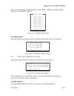
The hookswitch input can also be used to steer the source of transmit audio between
the “D” and “E” microphones. See Table 4-2 in Section 4 of this manual for more
information on the steering capabilities.
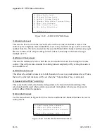
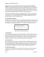
2) Instant Select Key Display Mode
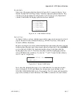
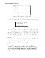
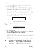
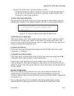
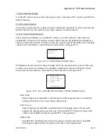
The menu shown in Figure D-50 allows you to pick the mode in which to show a selected
channel and/or frequency. This changes the display only; there is no operational difference.
A. Flashes Green LED for last selected Channel/Freq
B. Solid Green LED for selected Channel/Freq
Selection [ ]
Figure D-50. INSTANT SELECT KEY DISPLAY MODE Menu
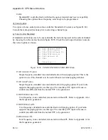
3) Received ‘CALL’ Light Duration
This selection allows you to set the length of time the channel “CALL” light (the red LED
associated with each Select key) remains on after the received audio stops. Enter a value
from zero to 60 seconds. Note that this time value is in addition to the hardware delay that is
always generated by the channel card itself.
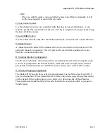
4) Dynamic Mic Selection
This feature determines the physical device assigned to the “D” Mic input. Choose either
“Gooseneck” or “Desk Mic”.
5) Parallel Remote Status Enabled
This feature allows two Model 4010 consoles that are interconnected through their COMB
serial ports to share common tone/DC remote function status.
Parallel status is only useful in systems using multiple remote functions on one or more
common channels. In this situation, changing a remote function on one Model 4010 console
updates the status on the other console if the same remote function has been programmed for
the same channel.
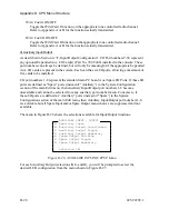
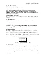
System Configuration
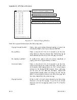
This section of programming allows the basic system to be defined or modified. This
includes the type of control for each channel, input/output definitions, paging mode
definitions, priority marker operation, transmitter timeout, and channel monitor configuration
(see Figure D-51).
Prior to configuring the system, it is imperative that the programmer has a complete
understanding of the radio system that is to be controlled by the Model 4010 console.
025-9229C.1
D-31
Summary of Contents for 4010
Page 2: ......
Page 4: ......
Page 7: ...1 INTRODUCTION HARDWARE REQUIREMENTS 1 1 DEFINITIONS 1 1 MANUALS 1 2...
Page 8: ......
Page 12: ......
Page 16: ...Section 2 Installation 2 4 025 9229C 1...
Page 18: ......
Page 34: ...Section 3 Tutorial 3 16 025 9229C 1...
Page 36: ......
Page 58: ......
Page 60: ......
Page 62: ......
Page 64: ......
Page 108: ...Appendix D CPS Menu Structure D 44 025 9229C 1...
Page 110: ......

