Section 4. Program Operation
025-9229C.1
4-7
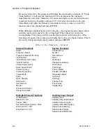
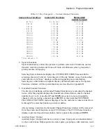
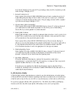
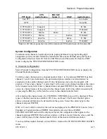
Table 4-2. Key Categories — Custom Channel Functions
Custom Tone Functions
Custom DC Functions
Motorola/GE
Control Currents*
No Tone
No Current
No Current
650 Hz
+ 2.5 mA
+ 2.5 mA
750 Hz
+ 5.0 mA
+ 5.5 mA
850 Hz
+ 7.5 mA
+ 6.0 mA
950 Hz
+10.0 mA
+11.0 mA
1050 Hz
+12.5 mA
+12.5 mA
1150 Hz
+15.0 mA
+15.0 mA
1250 Hz
+15.5 mA
+15.5 mA
1350 Hz
0.0 mA
0.0 mA
1450 Hz
- 2.5 mA
- 2.5 mA
1550 Hz
- 5.0 mA
- 5.5 mA
1650 Hz
- 7.5 mA
- 6.0 mA
1750 Hz
-10.0 mA
-11.0 mA
1850 Hz
-12.5 mA
-12.5 mA
1950 Hz
-15.0 mA
-15.0 mA
2050 Hz
-15.5 mA
-15.5 mA
*
(See Appendix C)
2.
3.
4.
System Functions
System function keys allow the operator to perform system level functions, such as
transmit, monitor, generate alert tones, all mute, simultaneous select, group select,
priority marker, and paging.
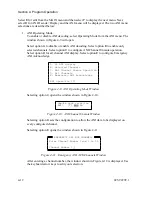
Selecting System Functions displays the SYSTEM FUNCTIONS menu with the
selections shown in Table 4-1. Selecting Alert, Priority Marker, or any function that
ends with the word “keys” displays a submenu requesting more information.
Selecting any other function completes the key definition and removes the System
Functions windows. All the system functions are described in Appendix D.
Extended Channel Functions
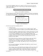
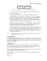
The first step in defining an Extended Channel Function key is selecting the channel
to use. After the program displays the channel selection windows, enter a channel
number from 1 to 14 or use the
UP
and
DOWN
arrow keys to move through the
channels. After selecting a channel press
ENTER
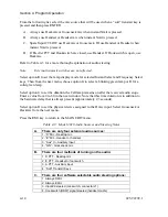
. At this point the EXTENDED
CHANNEL FUNCTIONS menu is displayed. Use the menu bar or enter a letter from
A
through
F
to select the function you wish to define.
After selecting a function, the Extended Channel Functions window will be removed
from the screen on all functions except CTCSS Select. The CTCSS Select function
displays a private line selection window. Select a private line and press
ENTER
.
Auxiliary Input / Output
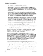
Auxiliary Input / Output ports have a variety of uses. Input ports can monitor alarms
or show voter status. Output ports can control gates, gas pumps, video monitors, room
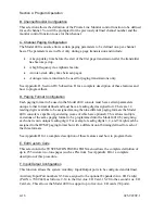
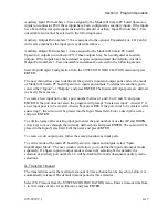
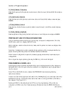
Summary of Contents for 4010
Page 2: ......
Page 4: ......
Page 7: ...1 INTRODUCTION HARDWARE REQUIREMENTS 1 1 DEFINITIONS 1 1 MANUALS 1 2...
Page 8: ......
Page 12: ......
Page 16: ...Section 2 Installation 2 4 025 9229C 1...
Page 18: ......
Page 34: ...Section 3 Tutorial 3 16 025 9229C 1...
Page 36: ......
Page 58: ......
Page 60: ......
Page 62: ......
Page 64: ......
Page 108: ...Appendix D CPS Menu Structure D 44 025 9229C 1...
Page 110: ......

