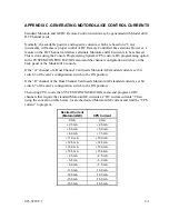
APPENDIX C. GENERATING MOTOROLA/GE CONTROL CURRENTS
Standard Motorola and GE DC Remote Control currents may be generated with Model 4010
DC Channel cards.
Normally, the available positive and negative currents, which are based on 2.5 mA
increments, will achieve proper control of DC Remote Controlled base stations. However, a
feature on the DC Channel card allows alternate Motorola and GE currents to be achieved.
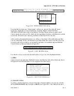
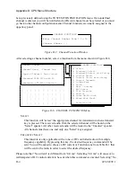
This is done using the Console Programming System (CPS) custom DC programming option
in the SYSTEM CONFIGURATION menu and the channel configuration switches on the
back panel of the Model 4010 console.
If the “A” channel of a Dual Channel Card needs Motorola/GE standard currents, set bit
switch 3 of the card’s configuration switch to the ON position.
If the “B” channel of the Dual Channel Card needs Motorola/GE standard currents, set bit
switch 7 of the card’s configuration switch to the ON position.
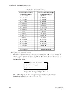
Then using CPS, locate the SYSTEM CONFIGURATION menu and program all DC
channels that require the standard Motorola/GE currents as “DC custom currents”. Then
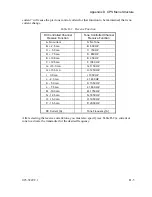
using the conversion table below, locate the desired Motorola/GE current and find the “CPS
current” to program.
Desired Current
(Motorola/GE)
CPS Current
0 mA
0 mA
+ 2.5 mA
+ 2.5 mA
+ 5.5 mA
+ 5.0 mA
+ 6.0 mA
+ 7.5 mA
+11.0 mA
+10.0 mA
+12.5 mA
+12.5 mA
+15.0 mA
+15.0 mA
+15.5 mA
+15.5 mA
- 2.5 mA
- 2.5 mA
- 5.5 mA
- 5.0 mA
- 6.0 mA
- 7.5 mA
-11.0 mA
-10.0 mA
-12.5 mA
-12.5 mA
-15.0 mA
-15.0 mA
-15.5 mA
-15.5 mA
025-9229C.1
C-1
Summary of Contents for 4010
Page 2: ......
Page 4: ......
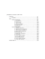
Page 7: ...1 INTRODUCTION HARDWARE REQUIREMENTS 1 1 DEFINITIONS 1 1 MANUALS 1 2...
Page 8: ......
Page 12: ......
Page 16: ...Section 2 Installation 2 4 025 9229C 1...
Page 18: ......
Page 34: ...Section 3 Tutorial 3 16 025 9229C 1...
Page 36: ......
Page 58: ......
Page 60: ......
Page 62: ......
Page 64: ......
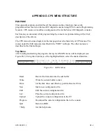
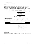
Page 108: ...Appendix D CPS Menu Structure D 44 025 9229C 1...
Page 110: ......

