


Section 4. Program Operation
025-9229C.1
4-17
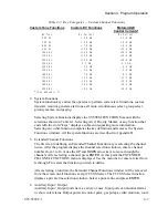
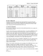
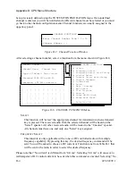
Auxiliary Input Port numbers 1-8 are assigned to the Model 4010 main PC board Spare/Aux.
inputs (on connector P8) if these inputs have been configured as auxiliary inputs. If the inputs
have been defined as spare inputs instead (the default), Auxiliary Input Port numbers 1-8 are
unavailable and cannot be selected in the following menus
Auxiliary Output Port numbers 9-38 are assigned to the optional Expanded Aux. I/O Card(s)
in the same manner as the input ports as described above.
Auxiliary Output Port numbers 1-8 are assigned to the Model 4010 main PC board
Spare/Aux. outputs (on connector P7) if these outputs have been configured as auxiliary
outputs. If the outputs have been defined as spare outputs instead (the default), Auxiliary
Output Port numbers 1-8 are unavailable and cannot be selected in the following menus.
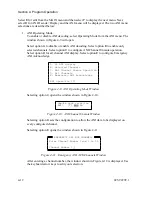
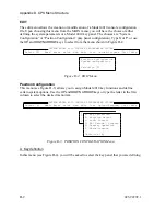
Select Input/Output Configuration from the SYSTEM CONFIGURATION menu and press
ENTER
.
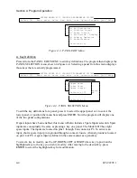
The next menu allows you to define all the system’s input and output ports and set the mode
of Model 4010 main PC board Spare/Aux. inputs and outputs. To define the auxiliary ports,
select either “Inputs” or “Outputs” and press
ENTER
. The Input and Output ports are defined
in exactly the same way.
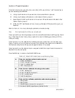
To create a new input port, enter a port number between 1 and 38 or 9 and 38, and press
ENTER
. If the port does not exist, the program will prompt “Create new input”. Answer
Y
if
a new input port is to be created. Answer
N
or press
ESC
if the port is not to be created. After
answering
Y
, the cursor will be placed into the Input Name field. Enter a descriptive name
and press
ENTER
.
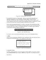
To edit the name of the existing input port, enter the port number or use the
UP
and
DOWN
arrow keys to move through the currently defined ports and press
ENTER
. The cursor will be
placed in the Input Name field. Edit the name and press
ENTER
.
To create or edit output ports, follow the same procedure as input ports.
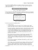
To set the mode of the main PC board Spare/Aux. inputs and outputs, select “Spare
Input/Output Mode”. The next window will allow you to define the input and output modes
separately. If a Spare input or output mode is chosen (by selecting
N
, the default), the
selection of auxiliary port numbers 1-8 will be disabled from all subsequent auxiliary menu
selections.
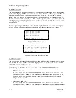
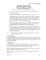
G. Transmit Timeout
The transmit timeout is the maximum amount of time a channel can be keyed up before it is
automatically released. The default timeout period is three minutes.
Select TX Timeout from the SYSTEM CONFIGURATION menu. Enter a timeout time from
1 to 10 minutes or zero for no timeout, and press
ENTER
.
Summary of Contents for 4010
Page 2: ......
Page 4: ......
Page 7: ...1 INTRODUCTION HARDWARE REQUIREMENTS 1 1 DEFINITIONS 1 1 MANUALS 1 2...
Page 8: ......
Page 12: ......
Page 16: ...Section 2 Installation 2 4 025 9229C 1...
Page 18: ......
Page 34: ...Section 3 Tutorial 3 16 025 9229C 1...
Page 36: ......
Page 58: ......
Page 60: ......
Page 62: ......
Page 64: ......
Page 108: ...Appendix D CPS Menu Structure D 44 025 9229C 1...
Page 110: ......


