Appendix D. CPS Menu Structure
Selection
D
is not implemented at the present time and defaults to selection
B
.
A
UXILIARY
O
UTPUT
I
NTERLOCKED
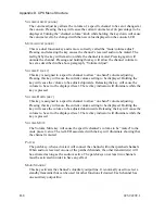
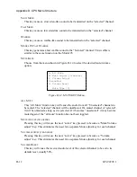
Several outputs may be “interlocked” such that only one output can be active at any
given moment. That is, when one output goes active, all others will be inactive. Up to
32 interlock groups may be defined with any number of outputs per group.
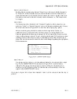
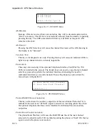
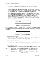
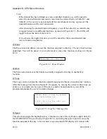
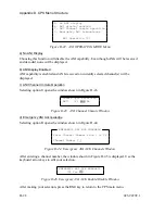
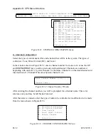
In the window shown in Figure D-30 enter the desired output number (up to 38), or
use the
UP
and
DOWN ARROW
keys to select the desired output number. The output
number will be accepted if it has been previously defined using the SYSTEM
CONFIGURATION menu. Output numbers 1 through 8 will only be allowed if the
main PC board Spare/Aux Outputs have been defined as “Auxiliary Outputs” in the
SYSTEM CONFIGURATION menu.
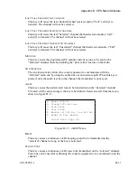
Output Number [ 1]
Output Name [door ]
Figure D-30. Output Number Window
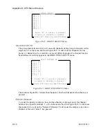
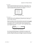
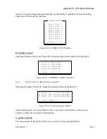
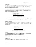
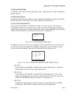
Type an interlock group number (1-32) in the window shown in Figure D-31. If the interlock
group has been already used, this input will be added to it; if not, a new interlock group will
be created.
Interlock Group [1_]
Figure D-31. Interlock Group Window
A
UXILIARY
O
UTPUT
T
OGGLE
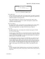
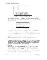
The chosen output will toggle with this key. That is, press the key once and the output
will be activated; press again and the output will deactivate.
A
UXILIARY
O
UTPUT
M
OMENTARY
As long as this key is pressed, the output will be active; when released, the output will
be inactive.
S
PARE
O
UTPUT
L
ATCHING
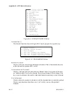
The eight spare outputs are located on connector 7 on the Model 4010 main PC board.
Note:
If Spare Outputs 7 and 8 are not programmed, they will function as follows:
Spare Output 7:
Will be ON whenever an ANI is displayed on the
console.
Spare Output 8:
Will produce a 500 ms pulse every time an ANI is
decoded
by
the
console.
D-22
025-9229C.1
Summary of Contents for 4010
Page 2: ......
Page 4: ......
Page 7: ...1 INTRODUCTION HARDWARE REQUIREMENTS 1 1 DEFINITIONS 1 1 MANUALS 1 2...
Page 8: ......
Page 12: ......
Page 16: ...Section 2 Installation 2 4 025 9229C 1...
Page 18: ......
Page 34: ...Section 3 Tutorial 3 16 025 9229C 1...
Page 36: ......
Page 58: ......
Page 60: ......
Page 62: ......
Page 64: ......
Page 108: ...Appendix D CPS Menu Structure D 44 025 9229C 1...
Page 110: ......

