


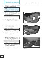


Fig. 2.4
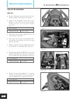
Fig. 2.5
COVER FRAME R & L
REMOVAL
l
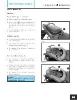
Remove the seats as explained earlier.
l
Remove the CRR pan head screw (M6x16 -
3 nos.) from the cover frame R. (Fig. 2.4)
Phillips head screw driver
l
Take out the cover frame R by carefully
dislocating it from the lugs.
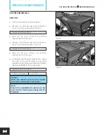
l
Remove the CRR pan head screw (M6x16 -
3 nos.) from the cover frame L. (Fig. 2.5)
Phillips head screw driver
l
Take out the cover frame L by carefully
dislocating it from the lugs.
l
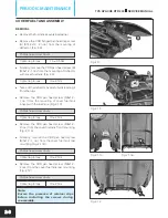
To reassemble the cover frame R & L, locate
the lugs of the cover frame at the holes
provided on the frame and install the CRR pan
head screw (M6x16 - 3 nos. each side).
Phillips head screw driver
Tightening torque
3 ± 1 Nm
Caution:
Make sure that the cover frame is locked
securely in position after installation.
Note:
Ensure the availability of cushions in the
cover frame 1front lug mounting area (at
fuel tank).
TVS APACHE RTR 200
SERVICE MANUAL
PERIODIC MAINTENANCE
2-4


