


l
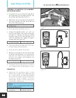
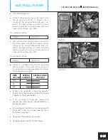
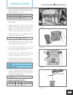
Turn ‘ON’ the ignition.
l
Connect the pocket tester’s ‘+ve‘ lead to the
orange grey wire (OrGr) of speed sensor
coupler at the wiring harness side and ‘–ve‘
lead to the black yellow wire (BY) of speed
sensor coupler at the wiring harness side and
measure the voltage. (Fig. 5.35)
The voltage should be:
Voltage
9 ± 1 Volt
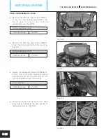
l
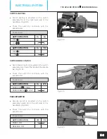
Then connect the pocket tester’s ‘+ve‘ lead to
the white green wire (WG) of speed sensor
coupler at the wiring harness side and ‘–ve‘
lead to the black yellow wire (BY) of speed
sensor coupler at the wiring harness side and
measure the voltage. (Fig. 5.36)
The voltage should be:
Voltage
5 ± 1 Volt
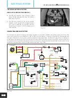
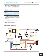
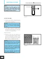
l
If there is no voltage output found in the speed
sensor coupler. Then check the continuity of
wiring harness between speed sensor coupler
and speedometer coupler
.
WIRE
SPEEDO
SPEED SENSOR
COLOUR COUPLER
COUPLER
OrGr
O
O
BY
O
O
GW
O
O
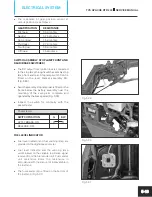
l
If there is no continuity in the wiring harness,
replace the wiring harness and check for speed
indication in the speedometer.
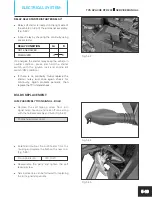
l
If the continuity is found OK, replace the
speedometer and check for speed indication in
the speedometer.
l
If the voltage is found OK while checking with
the pocket tester, then check speed senor in
the following manner:
l
Reconnect the speed sensor coupler.
l
Set pocket tester knob at DC 20 V range.
Fig. 5.36
TVS APACHE RTR 200
SERVICE MANUAL
ELECTRICAL SYSTEM
5-15
Fig. 5.35


