


Fig. 3.101
Fig. 3.102
Fig. 3.103
GEAR BOX ASSEMBLY, CRANK SHAFT
A S S E M B L Y A N D B A L A N C E R S H A F T
ASSEMBLY- SERVICING
l
Only to repair or replace gears, clutch shaft
assembly, drive shaft assembly, crankshaft
assembly and the balancer shaft assembly, the
crankcases need to be separated.
l
Remove the clutch assembly as explained
earlier (refer page no. 3-2 for removal
procedure).
l
Remove the cylinder head assembly, cylinder
block and piston as explained earlier (refer
page. 3-8 & 3-24 for removal procedure).
l
Refer chapter “Fuel lubrication and exhaust
system” page no. 4-16 for SAI unit removal
procedure.
REMOVAL OF ENGINE ASSEMBLY FROM THE
VEHICLE
l
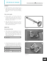
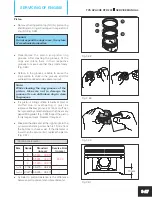
Remove hexagonal screw (M6x20 - 1 no.) from
the arm gear shifter lever mounting.
(Fig. 3.101)
10 mm spanner
Tightening torque
10 ± 2 Nm
l
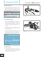
Gently pull out the gear shift lever from the
shaft assembly gear shift.
l
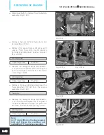
Remove CRR pan head screw (M6x20 - 2 nos.)
from the cover engine sprocket and take out
cover engine sprocket. (Fig. 3.102)
Philips head screw driver
Tightening torque
10 ± 2 Nm
l
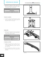
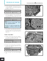
Remove hexagonal screw (M5x10 - 2 nos.)
from the lock plate engine sprocket mounting.
(Fig. 3.103)
8 mm spanner
Tightening torque
8 ± 1 Nm
l
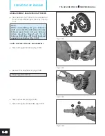
Take out the lock plate sprocket by rotating and
dislocating it from the shaft complete drive
grooves.
3-31
TVS APACHE RTR 200
SERVICE MANUAL
SERVICING OF ENGINE


