


l
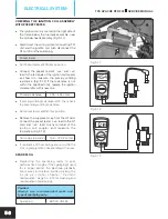
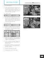
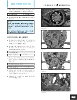
Connect the pocket tester’s ‘+ve‘ lead to the
orange grey wire (OrGr) and ‘–ve‘ lead to the
black yellow wire (BY) of speed sensor coupler
and measure the voltage. (Fig. 5.37)
The voltage should be:
Voltage
9 ± 1 Volt
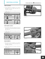
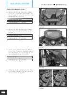
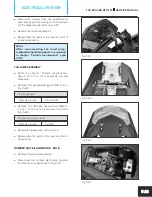
l
Then connect pocket tester’s ‘+ve‘ lead to the
white green wire (WG) and ‘–ve‘ lead to the
black yellow wire (BY) of speed sensor coupler
and measure the voltage. (Fig. 5.38)
The voltage should be either level A or level B.
LEVEL
VOLTAGE LEVEL
A
5 ± 0.5 Volt
B
0.1 ± 0.5 Volt
l
Now slowly rotate the rear wheel. If the
voltage indicated in the pocket tester is at
level A
then it should change to
level B
or vice
versa.
l
Now rotate the rear wheel little faster. If the
voltage indicated in the pocket tester is not as
per the specification. Then replace the speed
sensor and check the speedometer for proper
speed indication.
Voltage
2.5 ± 0.5 Volt
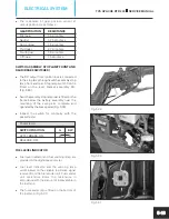
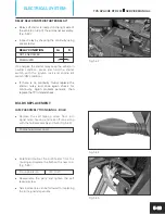
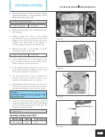
CHARGING PERFORMANCE CHECK
l
Set the pocket tester at DC 200 V range.
l
Remove the cover frame RH (refer chapter
“Periodic maintenance” page
for
no. 2.4
removal procedure).
l
Connect the pocket tester’s ‘+ve‘ lead of
pocket tester to positive terminal of the battery
and ‘–ve‘ lead of pocket tester to the negative
terminal of the battery. (Fig. 5.39)
l
Start and warm up the engine. Switch on the
head lamp high beam.
Fig. 5.39
TVS APACHE RTR 200
SERVICE MANUAL
ELECTRICAL SYSTEM
5-16
Fig. 5.37
Fig. 5.38


