
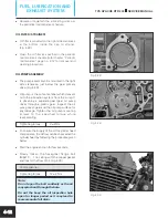


Fig. 5.5
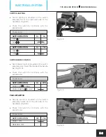
CONNECTING BATTERY
l
For battery disassembly or servicing, be sure
to disconnect the negative terminal first. When
connecting the terminals to the battery,
connect the negative terminal last.
l
If any terminal of the battery is found corroded,
remove the battery, pour warm water over it
and clean with wire brush.
l
Apply petroleum jelly on the terminals after
completion of connection and cover the
positive terminal with the boot. (Fig. 5.5)
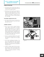
Fig. 5.6
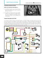
TVS Apache RTR 200 electrical system is divided in to four basic systems (circuits) named:
1. Ignition circuit 2. Lighting circuit 3. Charging circuit 4. Electric starter circuit
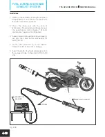
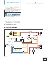
IGNITION SYSTEM
The ignition system of Apache RTR 200 consists of magneto assembly, regulator cum rectifier unit (RR unit), fuse
15A, battery, ignition lock, engine kill switch, TCI unit, ignition coil and a spark plug. (Fig. 5.6)
The output from the pulsar coil of magneto assembly is directly connected to the TCI unit. The DC output from the
battery is connected to the engine kill switch through a 15 amps fuse and through the ignition lock. The output of the
engine kill switch is connected to the TCI unit, ignition coil, relay starter and the self start switch.
TVS APACHE RTR 200
SERVICE MANUAL
ELECTRICAL SYSTEM
5-3
PULSAR COIL
Y
Y
Y
RR UNIT
12V, DC
BATTERY
12V, 9Ah
R
TO RELAY
STARTER MOTOR
TO RELAY STARTER /
SELF START SWITCH
R
BW
BW
R
R
R
W
Br
FUSE 15A (DC)
FUSE 10A
(HEAD LAMP)
TO OTHER CIRCUITS
ENGINE KILL
SWITCH
Or
Or
Or
OrB
OrB
IGNITION
LOCK
R
RB
OFF
ON
W
Br
TO SPEEDOMETER
MAGNETO ASSEMBLY
12V - 200W
Y
Y
Y
IGNITION COIL
HT CORD
SPARK
PLUG
BW
BW
BIR
WB
BIB
GR
GrR
P
WG
FROM ES SWITCH
FROM GEAR POSITION SENSOR
FOR HEAD LAMP OPERATION
TO STARTER RELAY
FROM CLUTCH SWITCH
FROM SPEEDOMETER
YB
TO SPEEDOMETER
(FOR TACHO INDICATION)
Bl
TCI UNIT
RW
RY
BBr
YOr
Ybl
WR
YB
OrB
Bl
THERMAL
SENSOR


