


Fig. 5.54
Fig. 5.56
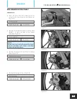
Fig. 5.55
TVS APACHE RTR 200
SERVICE MANUAL
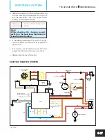
ELECTRICAL SYSTEM
5-22
l
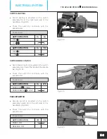
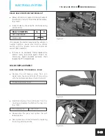
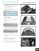
Remove the CRR flanged pan head tap screw
(ST4.2x13 - 3 nos.) and takeout the position
lamp assembly LH. (Fig. 5.54)
Phillips head screw driver
Tightening torque
1 ± 0.2 Nm
Position lamp
LED lamp (2W)
l
Replace the position lamp with a new one and
reassemble housing lamp front.
l
In similar manner the position lamp RH can be
removed and replaced.
l
Reassemble the parts in the reverse order of
removal.
Note:
After reassembling head lamp assembly,
readjust the head lamp beam as explained
in chapter
“Periodic maintenance” page
2-38).
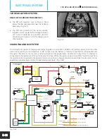
DIGITAL SPEEDOMETER ASSEMBLY
Since the digital speedometer is provided with
LED indicators, it is not possible to replace t h e m
individually. Recommended to replace the entire
speedometer assembly, incase of any failure.
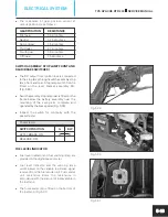
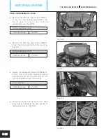
REMOVAL
l
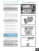
Remove the CRR pan head screw (M5x16 -
2 nos.) from the mounting of housing
speedometer rear and take out the housing
speedometer. (Fig. 5.55)
Phillips head screw driver
Tightening torque
3 ± 1 Nm
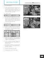
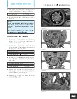
l
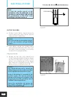
Remove the hexagonal nut (M6 - 3 nos.) along
with plain washers from the mounting of
speedometer assembly. (
)
Fig. 5.56
10 mm spanner
Tightening torque
3 ± 1 Nm


