


l
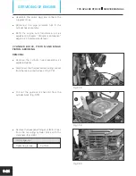
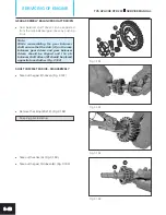
Take out key (4x4x15) from the crankshaft
assembly. (Fig. 3.128)
Nose plier
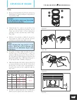
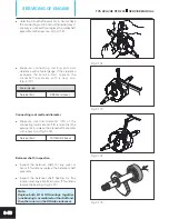
l
Using the special tool, hold the rotor assembly
as explained earlier and remove the hexagonal
flange nut (M12x1.25) from the balancer shaft
assembly. (Fig. 3.129)
17 mm spanner
Tightening torque
30 ± 5 Nm
Note:
Apply ANABOND 112 thread locker during
reassembly of the nut.
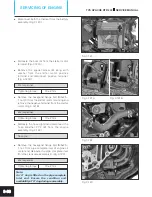
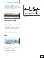
l
Using the special tool, hold the rotor assembly
and remove the rotor assembly mounting
hexagonal flange nut (M12x1.25). (Fig. 3.130)
N931 017 0
Magneto tool assembly
17 mm spanner
Tightening torque
80 ± 5 Nm
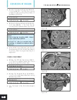
l
Using the special tool, remove the rotor
assembly along with gear complete starter
clutch. (Fig. 3.131)
M131 002 0
Puller assembly rotor
Note:
Always keep rotor assembly on a non
metallic surface with open side facing
upwards.
Fig. 3.128
Fig. 3.130
Fig. 3.129
Fig. 3.131
TVS APACHE RTR 200
SERVICE MANUAL
SERVICING OF ENGINE
3-38


