


Fig. 5.34
Fig. 5.33
l
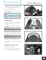
To inspect the fuel sender unit, fuel tank
complete must be removed (refer chapter
“Fuel, lubrication and exhaust system” page
no. 4-1 for removal procedure).
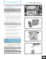
l
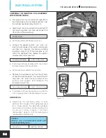
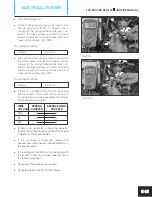
Inspect the fuel sender unit for continuity with
pocket tester by connecting ‘+ve' lead of
pocket tester to green yellow wire (GY) and
’-ve' lead to the black white wire (BW).
Pocket tester
l
Set pocket tester at 200 ohms position and
check the resistance of fuel sender unit. If the
resistance value is not within the specified
limit, replace the sender unit with new one.
(Fig. 5.
)
32
Full
4 ~ 6 ohms
Resistance
Empty 108 ~ 112 ohms
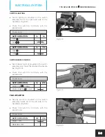
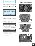
SPEED SENSOR
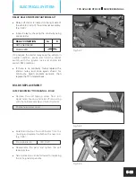
l
Speed sensor is mounted on the crank case LH
near engine sprocket. (Fig. 5.33)
To check the speed sensor:
l
Set pocket tester at DC 20 V range.
Pocket tester
l
Check and ensure the battery voltage is within
the specifications.
Battery voltage
12.9 volts
l
If the battery voltage is found less than the
specified voltage, recharge the battery as
explained in page no. 5-26.
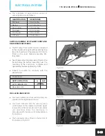
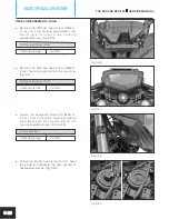
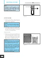
l
Disconnect the speed sensor coupler from the
main wiring harness. (Fig. 5.34)
Fig. 5.32
5-14
TVS APACHE RTR 200
SERVICE MANUAL
ELECTRICAL SYSTEM
EMPTY
FULL


