


l
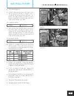
The resistance of gear position sensor at
various position are as follows:
GEAR POSITION
RESISTANCE
First gear
0.3 kilo ohms
Neutral
0.75 kilo ohms
Second gear
1.5 kilo ohms
Third gear
2.7 kilo ohms
Fourth gear
5.6 kilo ohms
Fifth gear
15 kilo ohms
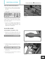
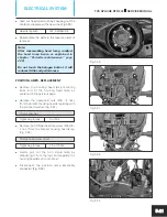
SWITCH ASSEMBLY STOP LAMP FRONT AND
REAR (BRAKE SWITCHES)
l
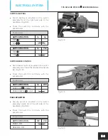
The DC output from ignition lock is connected
to the stop lamp through switch assembly stop
lamp front and rear. Stop lamp switch front is
fitted on the lever bracket assembly RH.
(Fig. 5.29)
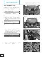
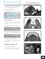
l
Switch assembly stop lamp rear is fitted on the
frame below the battery assembly near the
mounting of the swing arm complete and
operated by the brake pedal. (Fig. 5.30)
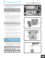
l
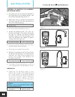
Inspect the switch for continuity with the
pocket tester.
Pocket tester
SWITCH POSITION
G
BW
APPLY BRAKE - ON
O
O
RELEASE - OFF
FUEL LEVEL INDICATOR
l
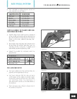
Fuel level indicator and fuel warning lamp are
provided in the digital speedometer.
l
Fuel level indicator and the warning lamp
works based on the variable resistance signal
received from the fuel sender unit. Fuel sender
unit resistance alters the resistance in
accordance with the amount of fuel available in
the fuel tank.
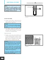
l
The fuel sender unit is fitted on the bottom of
the fuel tank. (Fig. 5.31)
Fig. 5.29
Fig. 5.30
Fig. 5.31
TVS APACHE RTR 200
SERVICE MANUAL
ELECTRICAL SYSTEM
5-13


