


PART 1: CX-Programmer
CHAPTER 4 – Reference
OMRON
CX-Programmer _Page 60
Program Editing
A number of procedures can be performed from within the Ladder program but it depends upon whether an
instruction, contact, coil, or workspace has been selected.
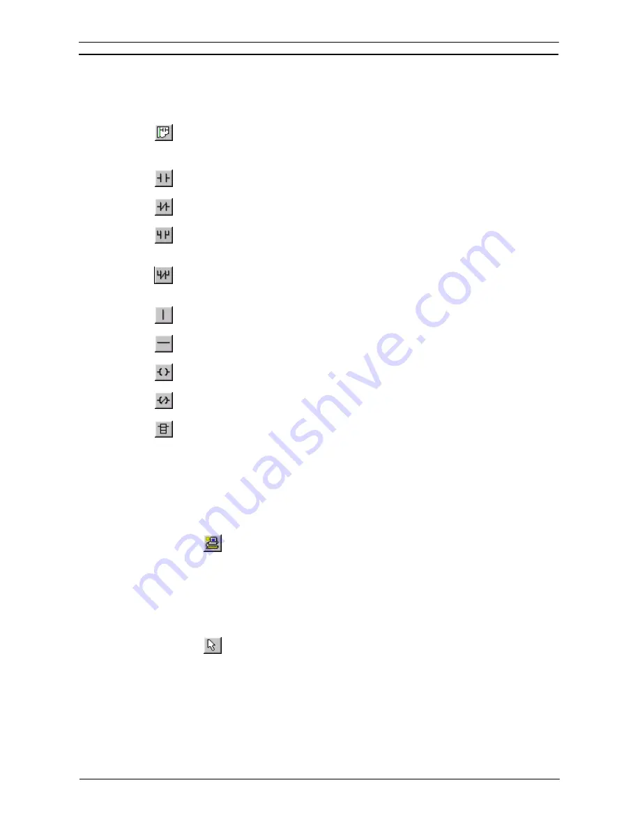
To view the Ladder program, select the View Diagram button from the toolbar.
The following elements can be selected from the
Diagram
toolbar and placed directly into the
Ladder program.
New Open Contact
. Once the Contact has been entered, the name or address for that contact
needs to be entered. Refer to
Chapter – 4 Contact and Coil Editing
for further information.
New Closed Contact
. Once the Contact has been entered, the name or address for that contact
needs to be entered. Refer to
Chapter – 4 Contact and Coil Editing
for further information.
New Open Contact OR
. Once the Contact has been entered, the name or address for that
contact needs to be entered. Refer to
Chapter – 4 Contact and Coil Editing
for further
information.
New Closed Contact OR
. Once the Contact has been entered, the name or address for that
contact needs to be entered. Refer to
Chapter – 4 Contact and Coil Editing
for further
information.
Vertical
. The
New Vertical
button from the toolbar connects elements in the Ladder program
vertically.
Horizontal
. The
New Horizontal
button from the toolbar connects elements in the Ladder
program horizontally.
New Open Coil
. Once the Coil has been entered, the name or address for that contact needs to
be entered, refer to
Chapter – 4 Contact and Coil Editing
for further information.
New Closed Coil
. Once the Coil has been entered, the name or address for that contact needs
to be entered, refer
Chapter – 4 Contact and Coil Editing
for further information.
Instruction
. Once the graphical instruction has been placed on the diagram, the actual
instruction must be selected, refer to
Chapter – 4 Contact and Coil Editing
for further
information.
Note that both a rung and elements of a program can be given comments within the ladder
display, by using
Properties
.
Use the following procedure to create a Ladder program.
1, 2, 3…
1. Select the PLC object in the project workspace.
2. From
the
Insert
menu select the
Program
option to start a new program. A
ladder editing window will open.
3. Select the Program object in the project workspace. Select the Program
object once more so it becomes an editable field. Enter a name for the
program.
4. Select one of the above objects from the Diagram toolbar and place on the
Ladder program. The icon image remains selected until another element is
clicked on the toolbar.
5. Items can be individually selected by selecting the Selection Mode button
from the toolbar.
6. Rungs can be selected by clicking the rung margin within the Ladder
program.
Some objects (excluding the rung and text comments, and the vertical and horizontals) have associated dialogs
allowing address or instruction information to be entered. Double-click on the object to redisplay the Edit
dialogue, this is dependent upon the selection.
The Auto Error Detection bar to the left of the rung indicates the validity of the entries.
It is possible to design a network and get the geometry right before entering specific symbol or address
information.
Summary of Contents for Sysmac WS02-CXPC1-EV3
Page 1: ...Cat No W414 E1 01 SYSMAC...
Page 2: ......
Page 3: ...SYSMAC WS02 CXPC1 EV3 CX Programmer Ver 3 1 Operation Manual Revised November 2002...
Page 4: ......
Page 6: ......
Page 7: ...PART1 CX Programmer...
Page 8: ......
Page 24: ......
Page 34: ......
Page 106: ......
Page 130: ......
Page 131: ...PART 2 CX Server PLC Tools...
Page 132: ......
Page 136: ......
Page 158: ......
Page 168: ......
Page 194: ......
Page 206: ......
Page 250: ......
Page 298: ......
Page 304: ......
Page 305: ...PART 3 CX Server Runtime...
Page 306: ......
Page 310: ......
Page 338: ......
Page 344: ......
Page 378: ......
Page 384: ......
Page 388: ......


