PART 3: CX-Server Runtime
CHAPTER 3 – Communications
OMRON
CX-Server Runtime_Page 18
specify the link information, a network type (e.g. SYSMAC LINK) and PLC addressing information is needed
(i.e. target network, node and unit).
Connection can be directly made to any PLC type. Direct connections are established with SYSMAC WAY,
Toolbus, Modem, Ethernet through a network card or SYSMAC NET, Controller Link or SYSMAC LINK via
an OMRON NSB.
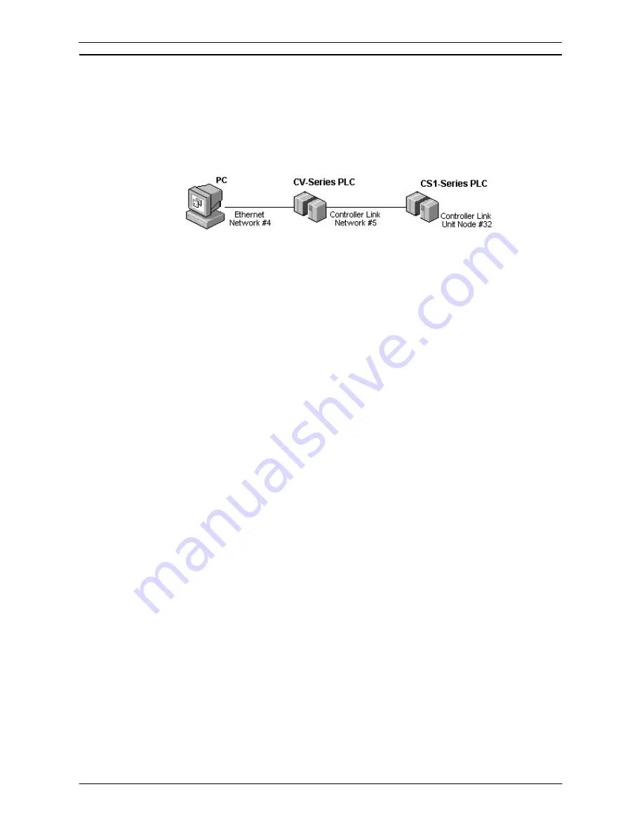
It is also possible to gateway from a direct connection on to another type of network that cannot be connected to
directly.
Use the following procedure to define a gateway connection.
1, 2, 3…
1. Open the Change PLC dialog.
2. Select the Gateway PLC (i.e. the direct connection). If necessary configure the CPU type
by selecting the associated
Settings
pushbutton.
3. Select
the
Network type
and click on the associated
Settings
pushbutton. The above
example uses Ethernet as the network.
4. The Network Settings dialog is displayed. Set up the address and Node number. For
Ethernet, also enter the IP address.
5. Select
the
OK
pushbutton to proceed from the Network Settings dialog.
6. Select
the
OK
pushbutton to proceed from the Change PLC dialog.
Use the following procedure to define a target connection.
1, 2, 3…
1. Add a PLC Device to the CX-Server project. The Change PLC dialog is reopened. Select
the PLC type for the target PLC. If necessary configure the CPU type by selecting the
associated
Settings
pushbutton.
2. Select the PLC to be used as the Gateway PLC from the list in the
Network Type
field and
click on the
Settings
pushbutton.
3. The Network Settings dialog is displayed. Set up the Source Network and Destination
Network and Node number.
4. Select
the
OK
pushbutton to proceed from the Network Settings dialog.
5. Select
the
OK
pushbutton from the Change PLC dialog to complete the operation or the
Cancel
pushbutton to abort the operation.
Serial Communications (Direct Connection)
The computer involved in establishing communications has at least one serial (RS232) port; the first port is
normally called COM1. If in doubt check the configuration of your PC. Only a single PLC can be connected to
an RS232 port.
For CS1-series PLCs, if Toolbus is being used as the direct connection, multiple destinations are permitted.
To establish a serial connection to several PLCs, Link Adapters are required that convert from RS232 to RS422.
Link Adapters would be connected in the serial line between the computer and the PLC or between the remote
Modem and the PLC. Multiple connections are permitted from an RS422 port.
If problems are experienced when making a serial connection, check the serial port on the computer is enabled
and that a mouse driver is not loaded or connected to the same port.
For PLCs with direct serial connections on the CPU, default communications settings can also be set by
changing the DIP switches on the front of the CPU. The default protocol settings are 9,600 baud, 7 data bits,
even parity and 2 stop bits. Older PLCs have a default baud rate of 2,400. For PLCs not supporting this feature,
settings are configured via the PLC Setup component. Refer to the
PLC Tools User Manual
Chapter 4 - PLC
Setup
Component for details of the PLC Setup component.
Summary of Contents for Sysmac WS02-CXPC1-EV3
Page 1: ...Cat No W414 E1 01 SYSMAC...
Page 2: ......
Page 3: ...SYSMAC WS02 CXPC1 EV3 CX Programmer Ver 3 1 Operation Manual Revised November 2002...
Page 4: ......
Page 6: ......
Page 7: ...PART1 CX Programmer...
Page 8: ......
Page 24: ......
Page 34: ......
Page 106: ......
Page 130: ......
Page 131: ...PART 2 CX Server PLC Tools...
Page 132: ......
Page 136: ......
Page 158: ......
Page 168: ......
Page 194: ......
Page 206: ......
Page 250: ......
Page 298: ......
Page 304: ......
Page 305: ...PART 3 CX Server Runtime...
Page 306: ......
Page 310: ......
Page 338: ......
Page 344: ......
Page 378: ......
Page 384: ......
Page 388: ......


