PART 1: CX-Programmer
OMRON
CHAPTER 4 – Reference
CX-Programmer _Page 61
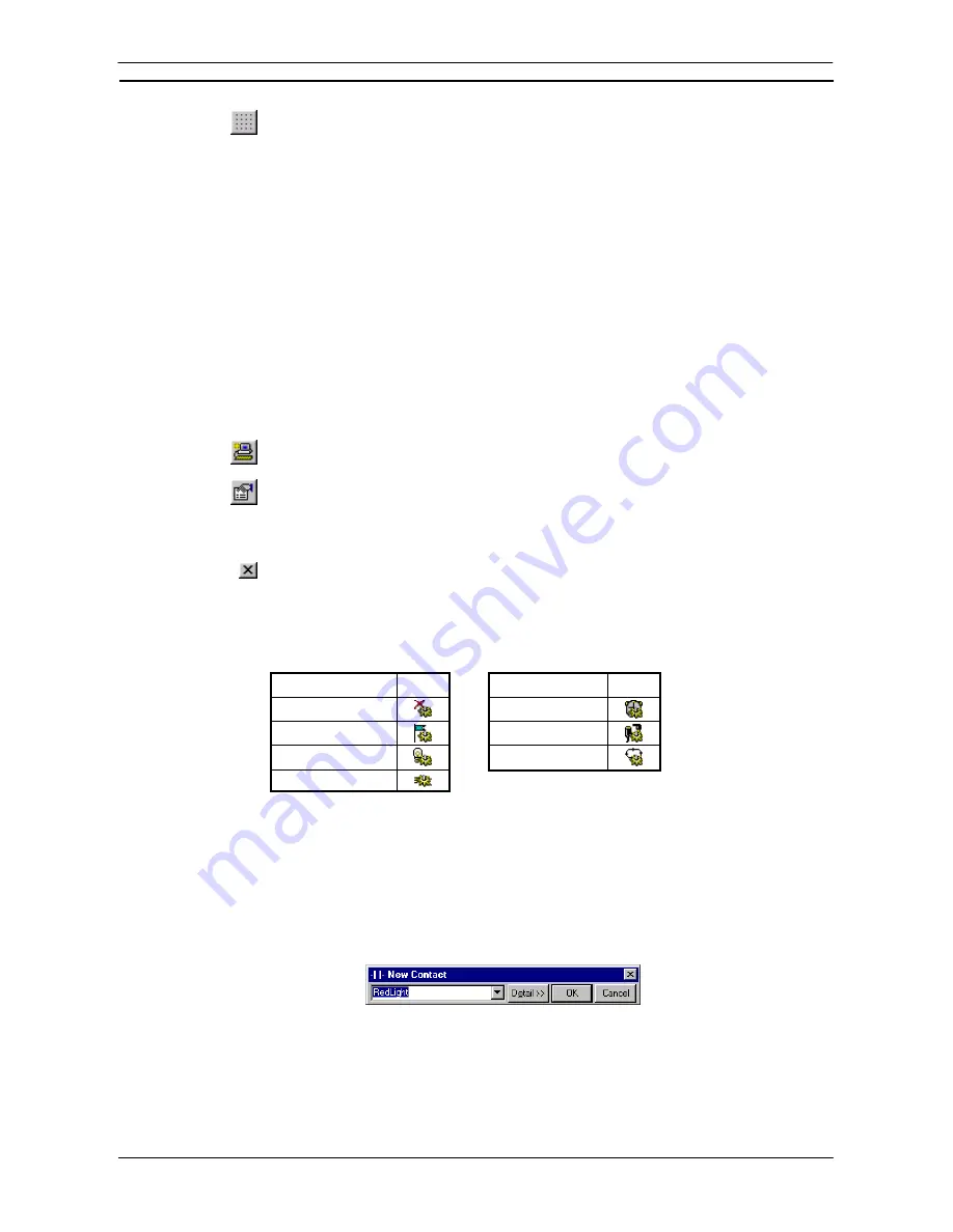
A Grid can be toggled on or off using by selecting the
Grid
button from the toolbar. When the
Grid is on, dots are displayed at the connection points of each cell in the program.
Program steps (graphically represented) are entered in a row or ladder ‘rung’ between the left (power supply)
and right (output) bus-bars.
Additional rows and columns can be inserted into the Ladder program via the
Insert Row
option and
Insert
Column
option from the context sensitive menu. Rows and columns can also be removed by selecting
Delete
Row
option and
Delete Column
option from the context sensitive menu.
By inserting Vertical Up or Vertical Down, rungs cannot be combined into one. To do this, select the rungs to
be combined and select
Combine
from the context sensitive menu. When a rung needs to be divided, select
Split
from the context sensitive menu to divide the rung into two.
Inserting a Program
A program is set up when the project is initially configured. For CS/CJ-series PLCs and CV-series PLCs, it is
possible to add multiple programs.
Use the following procedure to insert a program.
1, 2, 3…
1. To insert a new program, select the PLC object in the project workspace.
2. From
the
Insert
menu select the
Program
option. An empty Ladder program is placed in
the Diagram Workspace.
3. The task type associated with the program must be assigned (not for C-Series PLCs).
Select the program object in the project workspace and select the
Show Properties
button
from the toolbar. The Program Properties dialogue is displayed.
4. From
the
General
tab, select an option from the
Task Type
field.
5. Select
the
Close
button from the title bar to close the Program Properties dialogue.
The project is updated, showing a new program inserted at the bottom of the hierarchy together with an empty
local symbol table. Task types available are as follows (the icon is displayed next to the Program object in the
project workspace, and the task number is shown in brackets to the right).
Task Type
Icon
Task Type
Icon
Unassigned
Scheduled
Interrupt
Interrupt Task
IO
Interrupt
Power Off
Cyclic
Task
Power On
Contact and Coil Editing
The Edit Contact dialogue or Edit Coil dialogue allows the name or address of the contact or coil to be entered
or selected from a list of global and local symbols. The name or address can also be defined as a new symbol
from this dialogue and inserted into the local or global symbol table.
The dialog can be displayed in two forms, either:
simple dialog mode
or
detailed dialog mode
. The default
mode can be set in the
Diagram
tab in the
Options
dialogue. To change the
simple dialog mode
to a
detailed
dialog mode
, select
Detail
pushbutton.
Use the following procedure to edit contacts or coils in
simple dialog mode
.
1, 2, 3…
1. Double-click on the required contact in the Ladder program. The Edit Contact dialogue
or Edit Coil dialogue is displayed.
Summary of Contents for Sysmac WS02-CXPC1-EV3
Page 1: ...Cat No W414 E1 01 SYSMAC...
Page 2: ......
Page 3: ...SYSMAC WS02 CXPC1 EV3 CX Programmer Ver 3 1 Operation Manual Revised November 2002...
Page 4: ......
Page 6: ......
Page 7: ...PART1 CX Programmer...
Page 8: ......
Page 24: ......
Page 34: ......
Page 106: ......
Page 130: ......
Page 131: ...PART 2 CX Server PLC Tools...
Page 132: ......
Page 136: ......
Page 158: ......
Page 168: ......
Page 194: ......
Page 206: ......
Page 250: ......
Page 298: ......
Page 304: ......
Page 305: ...PART 3 CX Server Runtime...
Page 306: ......
Page 310: ......
Page 338: ......
Page 344: ......
Page 378: ......
Page 384: ......
Page 388: ......


