PART 1: CX-Programmer
OMRON
CHAPTER 4 – Reference
CX-Programmer _Page 75
Triggered:
When the pause is triggered, a trigger condition is necessary. A trigger
condition happens when the contents of an address reaches a certain value or makes a
transition.
It is possible to enter an address or a symbol name into the dialog, or browse for a symbol.
Select the type of condition, supplying the value or transition type.
When the pause monitoring function is operating, the display outside the selected region is
dimmed, and monitoring only occurs within the selected region.
Manually:
This option means that monitoring will only be paused when told to do so.
Select ‘Manually’ in the dialog and press ‘OK’. Monitoring then begins. To operate the
pause, wait until the monitoring screen is interesting, then select 'Pause' from the toolbar
or from the PLC/Monitor menu. The monitoring function is paused (the 'Pause' button on
the toolbar is shown as down). To resume monitoring, press the 'Pause' button again, and
monitoring will resume, waiting for another trigger.
If a condition is being used for pausing, the monitoring display will continue until the condition has been met, at
which point the 'Pause' button will be shown as down and monitoring freezes. To resume monitoring, and wait
for another instance of the condition, press 'Pause' again. Note that it is possible to manually pause the
monitoring by pressing 'Pause' even when using the ‘Triggered’ type of condition To resume full monitoring,
press the 'Pause Upon Trigger' button again, so that it is shown as out.
Stopping Pause Monitoring
Pause monitoring may be stopped by either taking the PLC off-line, taking the PLC out of monitor or run mode,
or by selecting pause monitoring again – This is effectively a toggle button.
On stopping pause monitoring, the hatched areas are removed and the PLC is either taken off-line, returned to a
normal on-line state or returned to normal monitoring or run mode.
The trigger condition that has been set is remembered should it be required to restart pause monitoring again in
the same session.
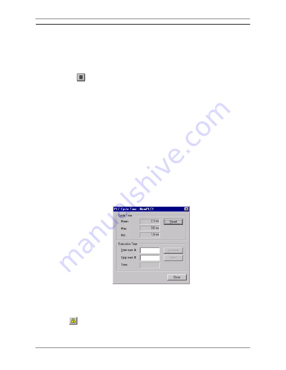
PLC Cycle Time
The PLC Cycle Time dialogue allows the PLC’s cycle times to be measured. The PLC Cycle Time is always
displayed in the status bar.
For certain CV-series PLCs if the ladder program contains Mark instructions, the PLC Cycle Time dialogue
permits the measurement between the Start Mark and Stop Mark instructions.
Use the following procedure to measure PLC cycle time.
1, 2, 3…
1. Select the PLC object in the project workspace.
2. Select
the
Work On-line
button from the toolbar. A confirmation message is displayed;
select the
Yes
pushbutton to connect to the PLC.
Summary of Contents for Sysmac WS02-CXPC1-EV3
Page 1: ...Cat No W414 E1 01 SYSMAC...
Page 2: ......
Page 3: ...SYSMAC WS02 CXPC1 EV3 CX Programmer Ver 3 1 Operation Manual Revised November 2002...
Page 4: ......
Page 6: ......
Page 7: ...PART1 CX Programmer...
Page 8: ......
Page 24: ......
Page 34: ......
Page 106: ......
Page 130: ......
Page 131: ...PART 2 CX Server PLC Tools...
Page 132: ......
Page 136: ......
Page 158: ......
Page 168: ......
Page 194: ......
Page 206: ......
Page 250: ......
Page 298: ......
Page 304: ......
Page 305: ...PART 3 CX Server Runtime...
Page 306: ......
Page 310: ......
Page 338: ......
Page 344: ......
Page 378: ......
Page 384: ......
Page 388: ......


