7-18
7-3 Normal Mode Autotuning
7
Adjustment Functions
5. Press the Increment key for approx. 3 s.
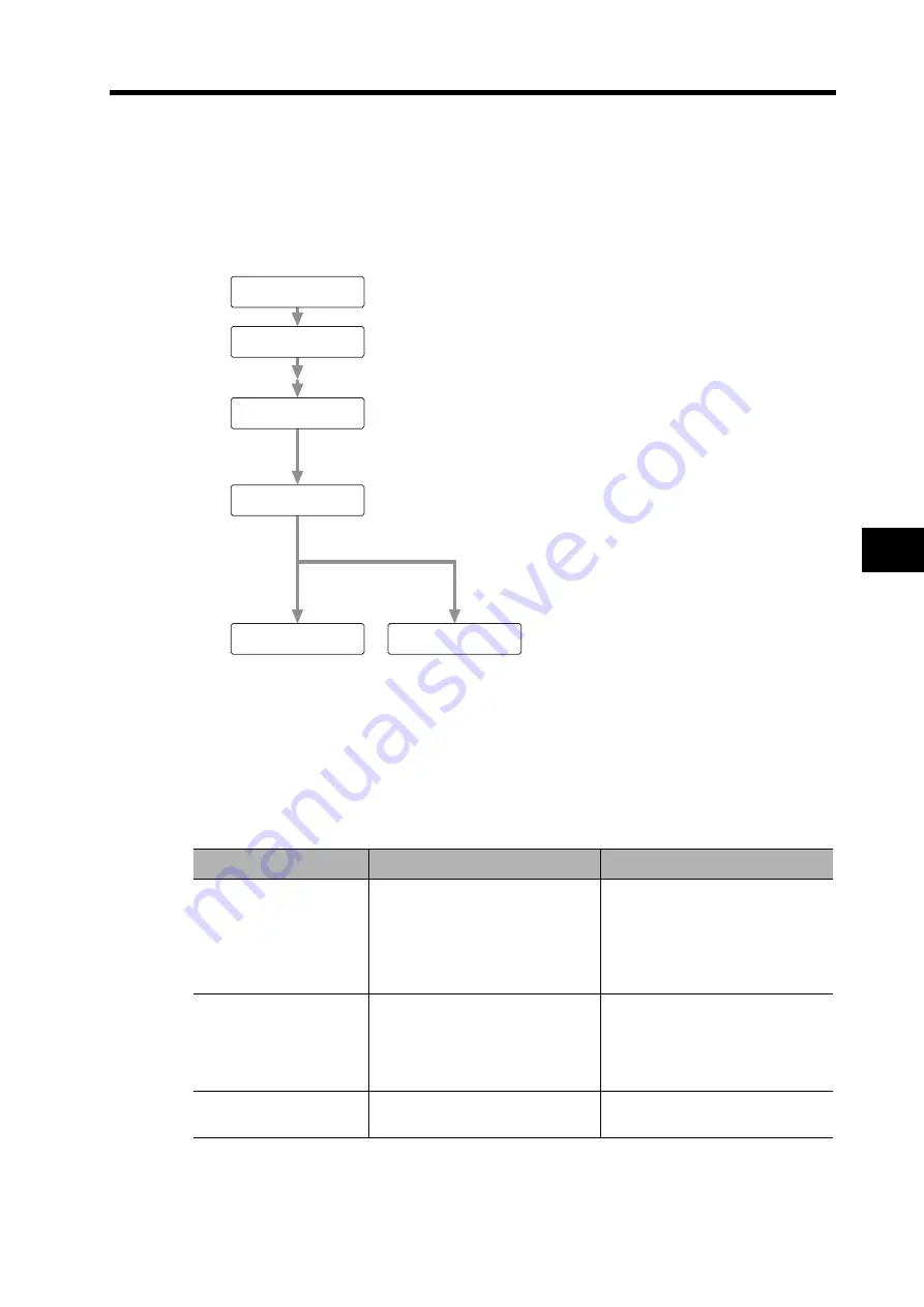
The bar indicator will increase as shown in the following figure.
The Servomotor will start to rotate.
For a period of approximately 15 s, the Servomotor will make two revolutions in the forward/reverse
direction, which will comprise one cycle and will be repeated up to five times. There is no problem
if operation ends before five cycles have been completed.
6. Write the data to the EEPROM so that the gain values are not lost when the power
supply is shut off.
• Do not perform normal mode autotuning with the Servomotor or Servo Drive alone. The Inertia
Ratio (Pn20) will become 0.
Precautions for Correct Use
Problem
Likely cause
Countermeasures
An error is displayed.
An alarm has occurred, the servo is
OFF, or the deviation counter is
reset.
•
Do not operate the Servomotor
near the Limit Switches or Origin
Proximity Sensor.
•
Turn the servo ON.
•
Release the deviation counter
reset.
Values for Pn10 or other
parameters related to gain
are the same as before
execution.
The load inertia cannot be
estimated.
•
Lower Pn10 to 10 and Pn11 to
50, and then execute again.
•
Make the adjustment manually.
(Input the calculated load
inertia.)
The Servomotor does not
rotate.
The ECRST (pin 30) of CN1 is input.
•
Turn OFF the ECRST (pin 30) of
CN1.
sktkakrktk
ekrkrkokrkkkk.
fkiknkikskh.
-k-k-k-k-k-.
aktkuk k-k-.
aktkuk k k-.
Tuning completed normally.
Tuning error occurred.
Summary of Contents for R88D-GT series
Page 20: ...18 Table of Contents ...
Page 234: ...3 133 3 8 Reactor Specifications 3 Specifications ...
Page 448: ...7 37 7 5 Manual Tuning 7 Adjustment Functions ...
Page 474: ...8 25 8 5 Periodic Maintenance 8 Troubleshooting ...
Page 475: ...Chapter 9 Appendix 9 1 Connection Examples 9 1 9 2 Parameter Tables 9 11 ...
Page 509: ......


