


5238-E P-46
SECTION 5 S, T, AND M FUNCTIONS
•
To rotate the M-tool spindle, the SB command must be specified in a block that precedes the
block containing the M-tool spindle start command or in the same block.
[Supplement]
3.
T Functions (Tool Functions)
[Function]
By specifying a 4-digit number (NC without tool nose radius compensation function) or a 6-digit
number (NC with tool nose radius compensation function) following address T, tool number, tool
offset number, and tool nose radius compensation number are indicated.
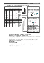
[Programming format]
LE33013R0300700040001
The setting ranges for nose radius compensation numbers and tool compensation numbers are as
follows:
(1) For offset 32-set specification
•
Tool offset number: 00 to 32
•
Tool nose radius compensation number: 00 to 32
(if tool nose radius compensation function is supported.)
(2) For offset 64-set specification
•
Tool offset number: 00 to 64
•
Tool nose radius compensation number: 00 to 64
(if tool nose radius compensation function is supported.)
(3) For offset 96-set specification
•
Tool offset number: 00 to 96
•
Tool nose radius compensation number: 00 to 96
(if tool nose radius compensation function is supported.)
[Details]
If there is a T command and an axis move command in the same block, the T command is executed
first and then the axis move command is executed.
[Supplement]
1) For the machine equipped with the transmission gears for driving the M-tool spindle, the
required gear range should be selected by a corresponding M code.
2) M-tool spindle rotation (forward, reverse) and stop are specified by M codes.
The construction of the turret and its direction of rotation (forward, reverse, shorter-path) vary
according to the machine specifications.
T
ΟΟ∆∆
ΟΟ
: Tool nose radius compensation number
∆∆
: Tool number (00 to 99, assuming maximum number of turret stations)
: Tool offset number


