


5238-E P-36
SECTION 3 MATH FUNCTIONS
[Supplement]
5.
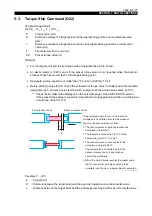
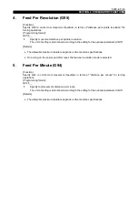
Torque Limit and Torque Skip Function
To transfer a workpiece from the first-process chuck to the second-process chuck with multi-process
models*, the end face of the second-process chuck jaws must be pushed against the workpiece for
stable workpiece seating. The torque limit command and the torque skip command are used to
control the torque of the second-process chuck feed servomotor and to push the workpiece with the
optimal thrust.
* Multi-process models include sub spindle models, opposing two-spindle models, etc.
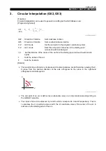
5-1.
Torque Limit Command (G29)
[Function]
Prior to workpiece transfer, designate the torque limit command to control the maximum torque of
the second-process chuck feed servomotor.
[Program Format]
G29 P D __
(Designate an axis to be fed: Z or W, for D.)
[Details]
•
The torque limit value is set as a percentage, taking the rated torque of the axis feed
servomotor as 100%.
•
The maximum torque limit value is set for optional parameter (OTHER FUNCTION 2).
5-2.
Torque Limit Cancel Command (G28)
[Function]
The torque limit cancel command cancels the maximum torque limit designated with G29.
When this command is designated, the axis feed motor can output its maximum output torque.
[Programming format]
G28
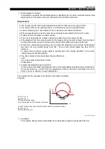
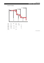
1) Both G75 and G76 are effective only in the G01 mode and if they are designated in a mode
other than G01an alarm occurs.
2) If the axis movement amount is smaller than the chamfering size, an alarm occurs.
3) Chamfering is possible only at corners between two lines. Chamfering at corners between two
arcs, between a line and an arc, or between an arc and a line is impossible. If chamfering at
such corners is attempted, an alarm occurs.
4) The chamfering command is effective both in the LAP and nose radius compensation mode.
5) If only an angle command A is designated in G00, G01, G34, or G35 mode operations, the next
axis movement command must contain A, X and Z commands so that the end point of the line
commanded can be defined. If these commands are not designated and the end point cannot
be defined, then an alarm occurs.
6) If chamfering commands G75 and G76 are designated without axis movement commands X
and Y or if they are designated only with an A command, the control reads the commands in
the next sequence to calculate the point of intersection automatically. Therefore, if the next
sequence does not contain adequate data for this calculation, an alarm occurs.


