

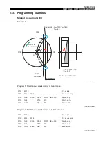
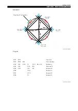


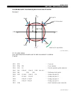


5238-E P-248
SECTION 9 CONTOUR GENERATION
The circular interpolation direction, tool nose radius compensation direction, and other factors
are determined based on the selected plane.
2-2.
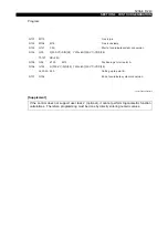
Programming Format
2-3.
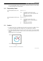
Cautions
•
An alarm occurs if the X coordinate value of the start and end points are different. This is
because the coordinate plane will be changed if the X coordinate values are different.
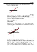
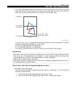
•
For circular interpolation between two points A and B on the side face, there are two possible
paths which have the same radius. In this case, the arc whose center angle is less than 180
°
is
selected.
In Fig. 5 below, the arc "a" is generated.
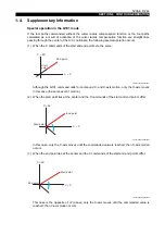
LE33013R0301100070001
Circular interpolation (CW) on side
face
: G132 Z C L F
Z, C :
Coordinates of end point for circular
interpolation (CW) on contour generation side
face
L :
Radius of arc on side face
F :
Cutting feedrate (mm/min)
Circular interpolation (CCW) on side
face
: G133 Z C L F
Z, C :
Coordinates of end point for circular
interpolation (CCW) on contour generation
side face
L :
Radius of arc on side face
F :
Cutting feedrate (mm/min)
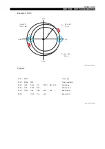
(C360) C0
(C0) C360
B
a
L
A
L
b
Fig. 5
The values in parentheses are for the inner plane.


