


5238-E P-185
SECTION 8 LATHE AUTO-PROGRAMMING FUNCTION (LAP)
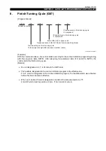
(3) The NAT01 command in block N0103 causes the control to search for the program assigned
the program name NAT01. A rough turning cycle in the bar turning mode is performed with this
program.
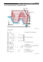
The cutting conditions for the rough turning cycle are also specified in the same block.
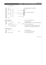
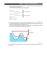
To change the cutting conditions during the rough turning cycle, designate the following
commands with G84.
To change the cutting conditions again, designate the following commands.
•
Cutting condition change points must be programmed in the block containing G85. For
clear programming, commands relating to such points are programmed in different lines,
each line preceded by the $ character which indicates that the line is a continuation of the
previous one.
•
When no F word is designated in this block, the feedrate commanded last is effective.
•
The point data of the cutting condition change points must become smaller in the following
order: AP starting point, XA, then XB, when performing OD turning. For ID turning, they
must become larger in this same order.
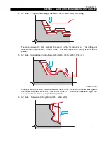
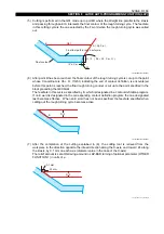
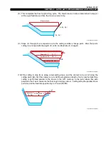
(4) Upon reaching the commands in block N0001, the control calculates the intersection point of
two straight lines: the line parallel to the Z-axis running at "Xs-D/2" and the one passing through
the two points (Xs, Zs) and (Xa + U, Za + W). Then, the axes are positioned at the calculated
point A (Xp, Zp).
Positioning is performed at the rapid feedrate when G00 is designated in the first block of the
contour definition blocks, and it is performed at a cutting feedrate when G01 is designated in the
first block of the contour definition blocks.
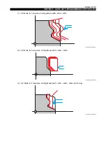
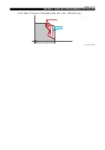
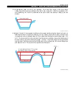
Select the AP starting point (Xs, Zs) with respect to the coordinated point (Xa, Za) to meet the
following requirements:
Xs < Xa for ID cutting
Xs > Xa for OD cutting
If the finish allowance U is made so large that "Xa + U" falls outside "Xs" with respect to the
workpiece, an alarm results.
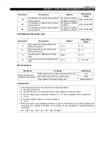
D
: Depth of cut
F
: Feedrate
U
: X component of stock removal in finish turning cycle
W
: Z component of stock removal in finish turning cycle
XA
: X coordinate of cutting condition change point A
DA
: Depth of cut after point A
FA
: Feedrate after point A
XB
: X coordinate of cutting condition change point B
DB
: Depth of cut after point B
FB
: Feedrate after point B


