
5238-E P-306
SECTION 12 USER TASK
3
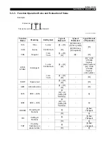
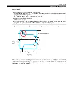
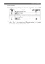
The elements (dimensions) used to define the contour, and the tool numbers and the cutting
speeds, are expressed using the local variables and the common variables, respectively.
LE33013R0301400490002
4
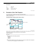
For cutting a workpiece, the LAP mode is used.
5
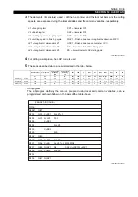
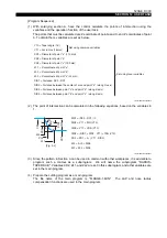
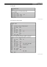
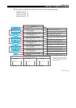
The steps described above are summarized in the table below.
•
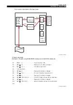
Subprogram
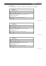
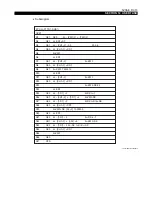
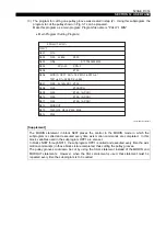
The subprogram defining the contour, prepared using local and common variables, can be
programmed as shown below on the basis of the table above.
LE33013R0301400490003
Roughing tool
Finishing tool
Cutting speed
in roughing
cycle
Cutting speed
in finishing
cycle
LZ1
LZ2
LZ3
DX1
DX2
DX3
WZ1
UX1
XS
ZS
V1
V2
V3
V4
LZ1
LZ2
LZ3
DX1
DX2
DX3
WLZ1
UDX1
XS
ZS
Workpiece A
Shaft-A
0101
0202
100
120
200
150
80
30
50
80
0.1
0.2
100
210
Workpiece B
Shaft-B
0303
0404
110
130
250
170
100
40
70
120
0.15
0.25
140
260
Workpiece C
Shaft-C
0505
0606
90
150
300
200
120
50
90
150
0.2
0.3
170
300
V1 = Roughing tool
V2 = Finishing tool
V3 = Cutting speed in roughing cycle
V4 = Cutting speed in finishing cycle
LZ1 = Longitudinal dimension LZ1
LZ2 = Longitudinal dimension LZ2
LZ3 = Longitudinal dimension LZ3
DX1 = Diameter DX1
DX2 = Diameter DX2
DX3 = Diameter DX3
WLZ1 = Finish allowance in longitudinal direction (WZ1)
UDX1 = Finish allowance on diameter (UX1)
XS = X coordinate of LAP starting point
ZS = Z coordinate of LAP starting point
O1000
NLAP1
N1001
N1002
N1003
N1004
N1005
N1006
N1007
N1010
N1011
N1012
N1020
N1021
N1022
F0.35 U=UDX1 W=WLZ1
Z=LZ1+2
F0.2
Z=LZ3
Z=0
Z=400
S=V3 T=V1 M03 M08
D4
Z=400
X=DX1
Z=LZ2
X=DX2
X=DX3
X=800
X=XS
NLAP1
X=800
NLAP1
G81
G00
G01
G80
G00
G96
G85
G00
G87
$ SHAFT-ABC.SUB %


